
Turning positioning mechanism for upper positioning of automobile welding hole and turning positioning mechanism for lower positioning of automobile welding hole

A positioning mechanism and welding hole technology, applied in welding equipment, auxiliary welding equipment, welding/cutting auxiliary equipment, etc. Effect

Pending Publication Date: 2018-11-06
芜湖安韬谱智能装备股份有限公司
View PDF17 Cites 0 Cited by
  • Summary
  • Abstract
  • Description
  • Claims
  • Application Information

AI Technical Summary

Problems solved by technology

[0007] The purpose of the present invention is to overcome the deficiencies in the prior art that the positioning accuracy of automobile welding is not high, and provide an overturn positioning mechanism for positioning on an automobile welding hole and an overturn positioning mechanism for down positioning. The overturn positioning mechanism for positioning on a hole of the present invention The hole position of the automobile sheet metal parts can be accurately positioned and clamped from above, and the flip positioning mechanism for lower positioning of the present invention can precisely position and clamp the hole positions of the automobile sheet metal parts from the bottom, fully ensuring the welding quality

Method used


Image

  • Turning positioning mechanism for upper positioning of automobile welding hole and turning positioning mechanism for lower positioning of automobile welding hole
  • Turning positioning mechanism for upper positioning of automobile welding hole and turning positioning mechanism for lower positioning of automobile welding hole
  • Turning positioning mechanism for upper positioning of automobile welding hole and turning positioning mechanism for lower positioning of automobile welding hole

Examples


Embodiment 1

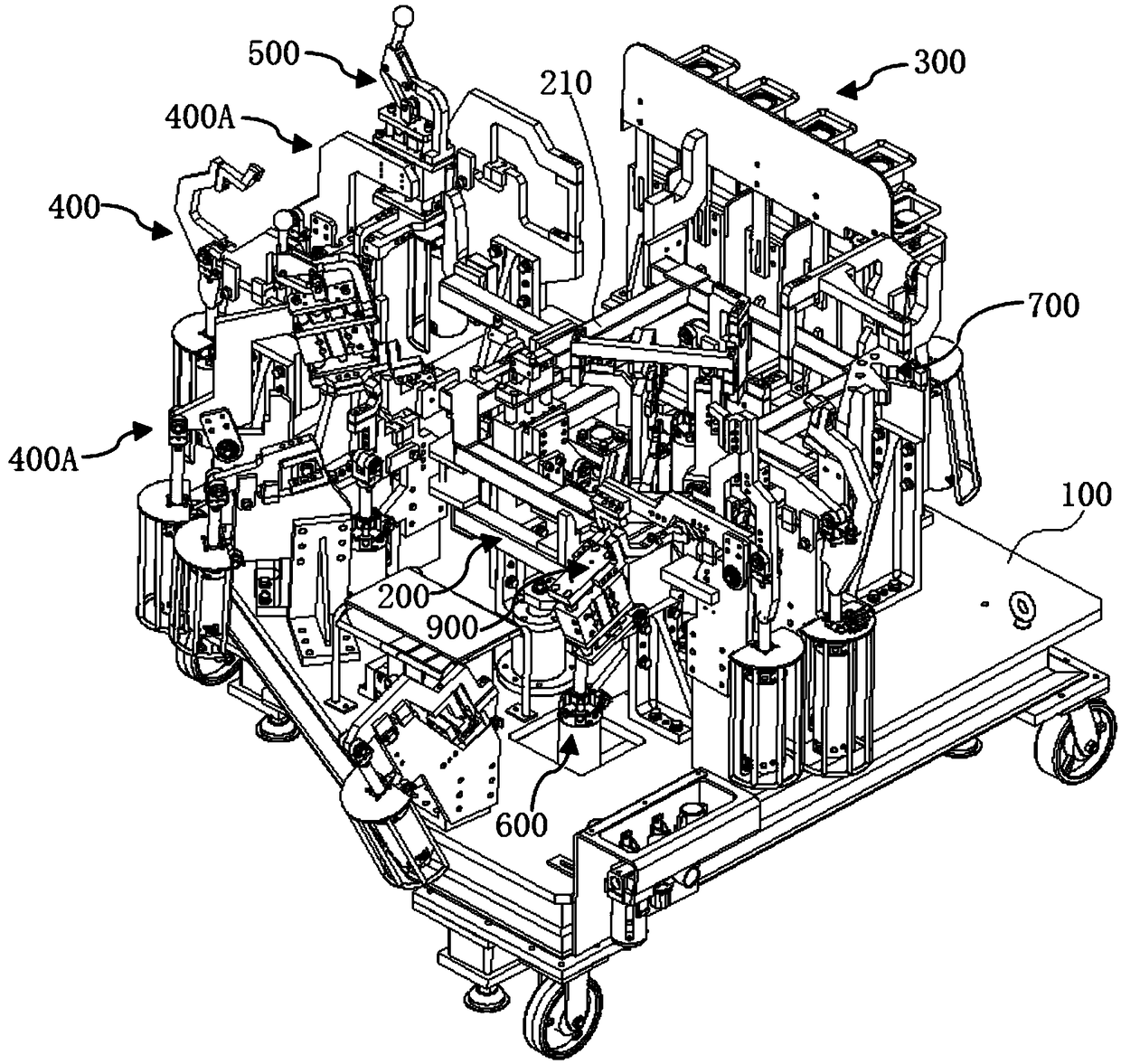
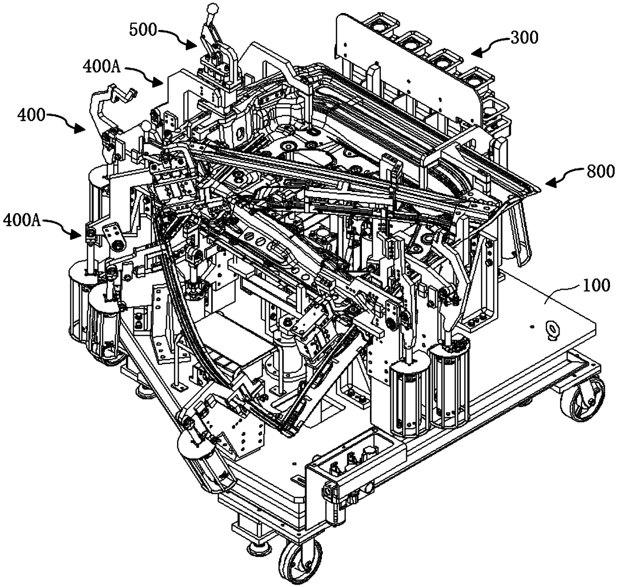
[0050] like Figure 5 and Figure 6 As shown, the flip positioning mechanism used for positioning on the welding hole of the automobile in this embodiment includes an upper hole jaw unit 400A for locking the hole position on the workpiece 800, and the top of the upper hole jaw unit 400A is provided with an upper hole positioning Unit 500, the upper hole jaw unit 400A in this embodiment includes an upper jaw cylinder 410, an upper jaw 440 is hinged on the top end of the telescopic rod of the upper jaw cylinder 410, and an upper connecting plate 420 is hinged on one side of the upper jaw cylinder 410 , the lower part of the upper jaw 440 is hinged with the upper connecting plate 420 through the upper hinge plate 430, and the top of the upper jaw 440 is provided with an upper hole positioning unit 500. Specifically, the lower part of the upper jaw 440 is fixedly connected with the upper hinge plate 430, and the upper hinge plate 430 is hinged with the upper connecting plate 420,...

Embodiment 2

[0054] The flip positioning mechanism used for positioning on the welding hole of the automobile in this embodiment has the same basic structure as that in Embodiment 1. Further, an upper movable plate 540 is arranged above the upper fixing seat 510 in this embodiment, and the upper movable plate 540 is arranged symmetrically on both sides. An upper guide post 512 is provided, and the upper guide post 512 passes through the upper fixing base 510 and is connected with the upper lifting plate 530 . When the upper telescopic rod 511 drives the upper lifting plate 530 to move up and down, the upper guide posts 512 on both sides move up and down in the upper fixed seat 510, and drive the upper movable plate 540 to lift up and down. The lifting motion of the upper positioning pin 532 is guided and positioned to ensure the accuracy and stability of the lifting direction of the upper positioning pin 532, and the positioning accuracy of the hole is further guaranteed to be improved.

...

Embodiment 3

[0057] The flipping positioning mechanism used for positioning on the welding hole of the automobile in this embodiment has the same basic structure as that in Embodiment 2. Furthermore, in this embodiment, the upper support plate 520 along the length direction of the V-shaped groove of the first positioning seat 522 has two First positioning holes 524 are respectively arranged on the sides, second positioning holes 525 are respectively arranged on both sides of the upper supporting plate 520 along the length direction of the V-shaped slot of the second positioning seat 523, and correspondingly provided on the upper movable plate 540 are respectively The first positioning hole 524 and the second positioning hole 525, a first positioning column is arranged between the corresponding two first positioning holes 524 on the upper movable plate 540 and the upper supporting plate 520, and the upper movable plate 540 and the upper supporting plate 520 A second positioning column is dis...


PUM


Abstract

The invention discloses a turning positioning mechanism for upper positioning of an automobile welding hole and a turning positioning mechanism for lower positioning of the automobile welding hole, and belongs to the field of automobile welding. The turning positioning mechanism for upper positioning comprises an upper hole clamping jaw unit used for locking a hole position on a workpiece, an upper hole positioning unit is arranged at the top end of the upper hole clamping jaw unit, the upper hole clamping jaw unit comprises an upper clamping jaw air cylinder, an upper clamping jaw is hinged to the top end of a telescopic rod of the upper clamping jaw air cylinder, an upper connecting plate is hinged to one side of the upper clamping jaw air cylinder, the lower portion of the upper clamping jaw is hinged to the upper connecting plate through an upper hinge plate, and the upper hole positioning unit is arranged at the top end of the upper clamping jaw. According to the turning positioning mechanism for upper positioning of the automobile welding hole and the turning positioning mechanism for lower positioning of the automobile welding hole, the defect that in the prior art, the automobile welding positioning precision is not high is overcome, sheet metal parts can be precisely positioned and clamped, and the welding quality is guaranteed.

Description

technical field [0001] The invention relates to the technical field of automobile welding, and more specifically, relates to an overturn positioning mechanism for upper positioning of an automobile welding hole and an overturn positioning mechanism for down positioning. Background technique [0002] Now China's automobile manufacturing industry is developing rapidly and has gradually become one of the pillar industries of our country. In the automobile manufacturing process, the welding of sheet metal parts is an important process. In the whole welding operation, it is necessary to use a special clamping system to realize fast loading / unloading of sheet metal parts, and Finally, the sheet metal parts are effectively fixed and positioned to ensure the welding accuracy. Therefore, the welding clamping system is a very important auxiliary tool, which not only affects the accuracy of the welding processing position and welding quality, but also affects work efficiency and produc...

Claims


Application Information

Patent Timeline
Patent Type & Authority Applications(China)
IPC IPC(8): B23K37/04
CPCB23K37/0435
Inventor 石成凯何从好袁开
Owner 芜湖安韬谱智能装备股份有限公司
Learn More