Automatic steel structure installing equipment and automatic installation construction method thereof

An automatic installation, steel structure technology, applied in the direction of hoisting device, portable lifting device, etc., can solve the problem that the channel steel cannot be locked in all directions, stuck between two I-beams, and the welding height can be adjusted manually. question

Active Publication Date: 2018-11-06
安徽精工钢结构有限公司
View PDF12 Cites 6 Cited by
  • Summary
  • Abstract
  • Description
  • Claims
  • Application Information

AI Technical Summary

Problems solved by technology

[0004] In order to solve the above problems, the present invention provides a steel structure automatic installation equipment and its automatic installation and construction method, which can solve the existing problems in the construction of steel structure partitions that the channel steel needs to be manually taken, and the channel steel is dropped when taken. It is necessary to manually flip the channel steel to a suitable welding angle. The channel steel cannot be locked in all directions when it is placed and conveyed. The welding height of the channel steel needs to be adjusted manually. When the channel steel is placed, it will be stuck in two There will be deviations between the I-be

Method used


Image

  • Automatic steel structure installing equipment and automatic installation construction method thereof
  • Automatic steel structure installing equipment and automatic installation construction method thereof
  • Automatic steel structure installing equipment and automatic installation construction method thereof

Examples


Embodiment Construction

[0039] In order to make the technical means, creative features, goals and effects achieved by the present invention easy to understand, the present invention will be further described below in conjunction with specific illustrations. It should be noted that, in the case of no conflict, the embodiments in the present application and the features in the embodiments can be combined with each other.

[0040] Such as Figure 11As shown, the existing steel structure partition I-beam and channel steel are connected by welding, and the channel steel is evenly arranged perpendicular to the I-beam.

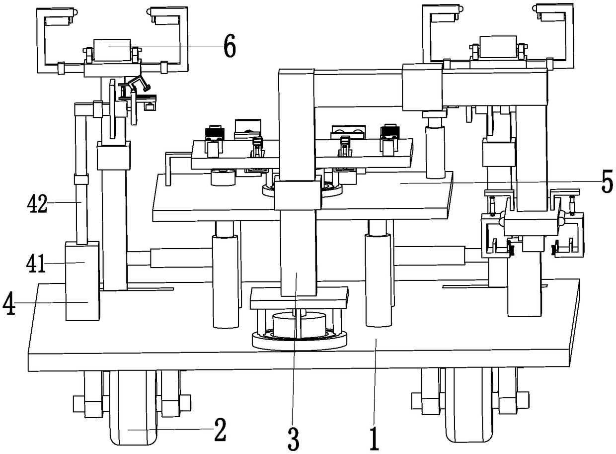
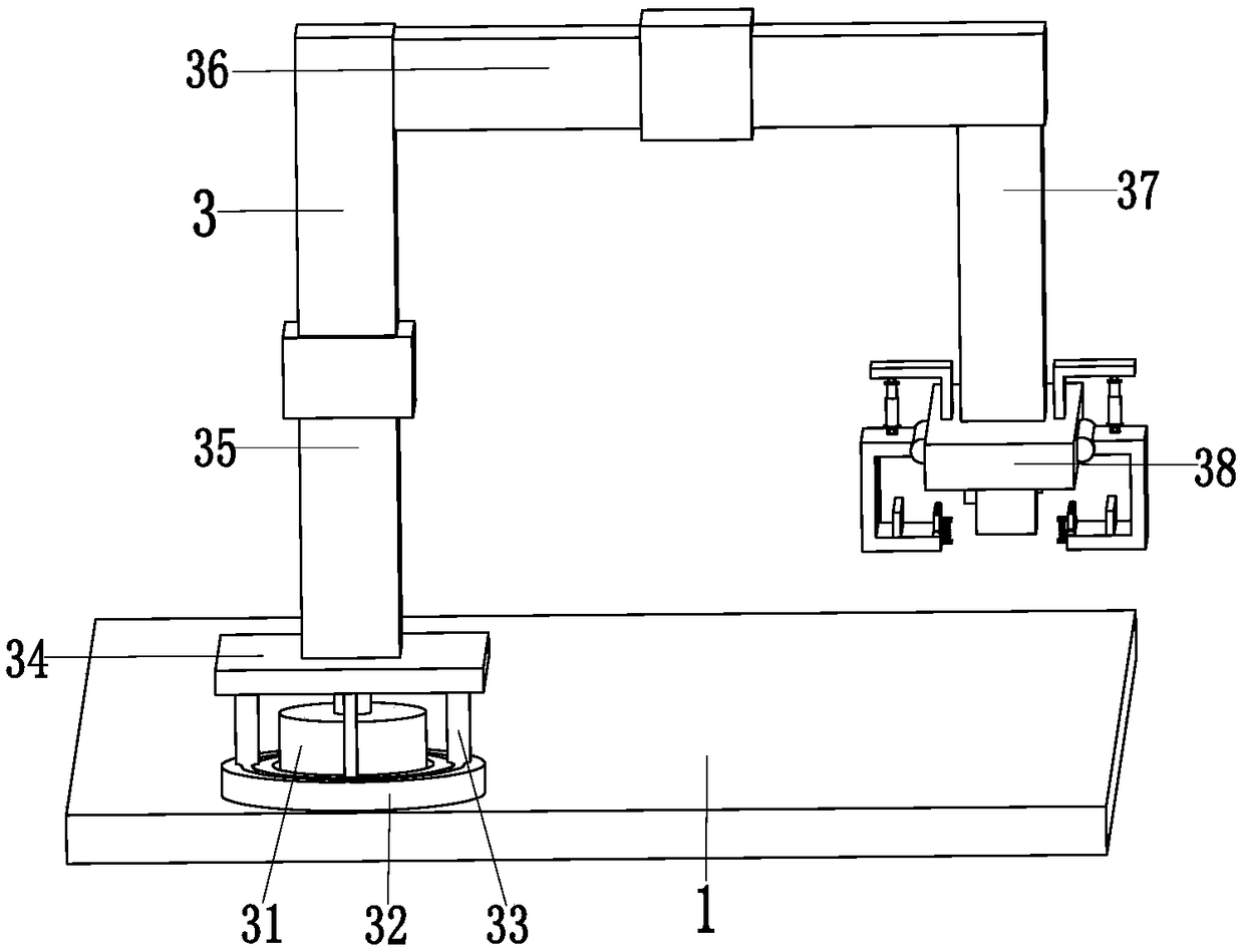
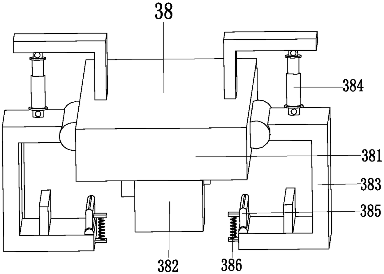
[0041] Such as Figure 1 to Figure 10 As shown, a steel structure automatic installation equipment includes a support base plate 1, a walking wheel 2, a lifting device 3, a placement device 4, a lifting device 5 and a positioning device 6, and the rear end top of the support base plate 1 is symmetrical A chute is provided, and the traveling wheels 2 are symmetrically installed on the botto...


PUM


Abstract

The invention relates to automatic steel structure installing equipment and an automatic installation construction method thereof. A supporting base plate, walking wheels, a hoisting device, arrangement devices, a lifting device and positioning devices are included, the walking wheels are symmetrically installed on the bottom of the supporting base plate, the hoisting device is installed on the top of the front end of the supporting base plate, the lifting device is installed at the middle portion of the supporting base plate, the left and right ends of the lifting device are each provided with one arrangement device, the arrangement devices are installed on the top of the outer end of the supporting base plate, and the positioning devices are symmetrically installed at the top of the backend of the supporting base plate. By means of the automatic steel structure installing equipment and the automatic installation construction method, the problems that during existing steel structurepartition wall construction, the box iron falling risk exists when box iron is taken, the box iron needs to be manually overturned to the appropriate welding angle, all-dimensional locking of the boxiron cannot be achieved during arrangement and conveying, the box iron welding and arrangement height needs to be manually adjusted, the box iron can be clamped between two pieces of joist steel whenarranged, and the box iron welding and arrangement position may have deviations are solved.

Description

technical field [0001] The invention relates to the technical field of steel structure construction, in particular to a steel structure automatic installation device and an automatic installation construction method thereof. Background technique [0002] Due to the rise of apartment-type residences, high-ceilinged houses are particularly popular, especially young people now love to raise the house type. When decorating apartments, it is necessary to carry out construction work on the layered partitions of the decoration. The partitions of apartments are basically pre-prepared. There are supporting I-beams buried. These I-beams play a supporting role. The partition construction needs to weld channel steel between two adjacent I-beams. After the construction of the partition steel structure is completed, it needs to be laid on the partition steel structure. Processes such as planks, such as Figure 11 As shown, the existing steel structure partition I-beam and channel steel ar...

Claims


Application Information

Patent Timeline
IPC IPC(8): B66D3/20B66D3/26
CPCB66D3/20B66D3/26
Inventor 潘春燕
Owner 安徽精工钢结构有限公司
Why Eureka
Try Eureka