Eureka AIR delivers breakthrough ideas for toughest innovation challenges, trusted by R&D personnel around the world.

Tunnel deformation joint structure and construction method thereof

A technology for tunnel structure and deformation joints, which is applied in tunnels, tunnel linings, earthwork drilling and mining, etc. It can solve problems such as difficulty in maintaining standard width of gaps, excessive deformation difference, and impact on tunnel normal operation safety, etc., to achieve quality control and construction convenient effect

Pending Publication Date: 2019-11-12
CHINA RAILWAY SIYUAN SURVEY & DESIGN GRP
View PDF0 Cites 5 Cited by
  • Summary
  • Abstract
  • Description
  • Claims
  • Application Information

AI Technical Summary

Problems solved by technology

The deformation joint structure can generally meet the differential deformation requirements of the longitudinal structure of the tunnel, but there are still the following problems in application: (1) The water receiving box used for waterproofing the deformation joints of the tunnel is easy to fall off after aging, which affects the normal operation safety in the tunnel; (2) The gaps between the deformation joints of the tunnel are generally filled with foam materials after the construction of the first pouring section. After the pouring section of the structure is poured, the foam is taken out to fill the gaps. It is difficult to maintain the standard width of the gaps in the deformation joints with this structure , it often occurs that during the pouring process of the structures on both sides of the gap, the interface on both sides loses the function of the deformation joint after being close to each other; (3) The displacement and deformation on both sides of the deformation joint are not easy to control, and the deformation difference may be too large, which will affect the normal operation of the tunnel

Method used


Image

  • Tunnel deformation joint structure and construction method thereof
  • Tunnel deformation joint structure and construction method thereof
  • Tunnel deformation joint structure and construction method thereof

Examples


Embodiment Construction

[0029] The following will clearly and completely describe the technical solutions in the embodiments of the present invention with reference to the accompanying drawings in the embodiments of the present invention. Obviously, the described embodiments are only some, not all, embodiments of the present invention. Based on the embodiments of the present invention, all other embodiments obtained by persons of ordinary skill in the art without making creative efforts belong to the protection scope of the present invention.

[0030] In describing the present invention, it is to be understood that the terms "center", "upper", "lower", "front", "rear", "left", "right", "vertical", "horizontal", The orientations or positional relationships indicated by "top", "bottom", "inner", "outer", etc. are based on the orientations or positional relationships shown in the drawings, and are only for the convenience of describing the present invention and simplifying the description, rather than in...


PUM


Abstract

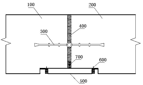
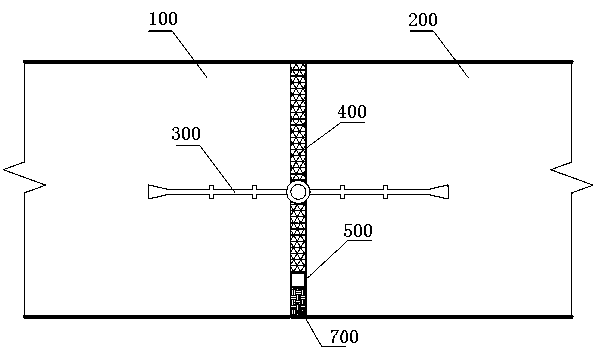
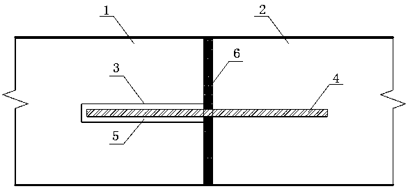
The invention belongs to the technical field of tunnel engineering, and particularly relates to a tunnel deformation joint structure. The tunnel deformation joint structure comprises a tunnel structure pre-casting section and a tunnel structure post-casting section. A viscous waterproof material is arranged in a deformation joint between the tunnel structure pre-casting section and the tunnel structure post-casting section; a steel sleeve with an opening toward the tunnel structure post-casting section is embedded in the tunnel structure pre-casting section, a steel bar is inserted in the steel sleeve, and one end of the steel bar passes through the viscous waterproof material and is anchored into the tunnel structure post-casting section. The invention further provides a construction method of the tunnel deformation joint structure. The construction method comprises the steps that construction of the tunnel structure pre-casting section is conducted at first and the steel sleeve is buried, and the viscous waterproof material is affixed on a cross section; then the steel sleeve is filled with butter and the like, and one end of the steel bar is inserted into the steel sleeve; and then construction of the tunnel structure post-casting section is conducted, and the steel bar is anchored into the tunnel structure post-casting section. By arranging the viscous waterproof material in the deformation joint, through viscosity of the material and the anchoring effect of the steel bar, deformation joint filler and a water receiving box can be prevented from dropping, and the construction process is simple and of high quality.

Description

technical field [0001] The invention belongs to the technical field of tunnel engineering, and in particular relates to a deformation joint structure and a construction method of a mining method tunnel. Background technique [0002] The tunnel structure is located at the opening, light-dark boundary, and changes in surrounding rock conditions. Due to the different properties of the surrounding rock in different strata, the tunnel structure often has longitudinal deformation differences during the operation period. The structural deformation difference may cause structural cracking and damage. It is necessary to set the deformation The joints are used to offset the impact of the displacement difference of the tunnel structure and ensure the safety of the structure. In the deformation joints of existing tunnels, a gap of 2 to 3 centimeters is generally adopted between the lining structure 100 of the pouring section and the lining structure 200 of the post-casting section, wate...

Claims


Application Information

Patent Timeline
Patent Type & Authority Applications(China)
IPC IPC(8): E21D11/38E21D11/14E21D11/10
CPCE21D11/38E21D11/14E21D11/10
Inventor 薛光桥肖明清杨剑李达
Owner CHINA RAILWAY SIYUAN SURVEY & DESIGN GRP
Why Eureka
Eureka Blog
Learn More