Dynamic and static pressure mixing lubricating end face sealing structure

A hybrid lubrication and end-face sealing technology, applied in the direction of engine seals, engine components, mechanical equipment, etc., can solve problems such as inability to meet, and achieve the effect of improving stiffness and stability

Active Publication Date: 2018-11-06
XI AN JIAOTONG UNIV
View PDF6 Cites 17 Cited by
  • Summary
  • Abstract
  • Description
  • Claims
  • Application Information

AI Technical Summary

Problems solved by technology

[0006] The purpose of the present invention is to provide a dynamic and static pressure mixed lubrication end face seal structure, which is used for reducing the shaft end leakage (or even zero leakage), improving the operation efficiency and safety and stability of the turbomachinery, and the dry gas seal cannot meet the requirements. The problem of shaft seal requirements under start-stop, variable working conditions and extreme conditions, which has porous media friction pairs, lubricating gas passages, lubricating gas stabilizing chambers and high-precision displacement sensors Ring, which can realize the dynamic and static pressure mixed gas lubrication end face sealing structure of dynamic pressure gas lubrication and static pressure gas lubrication, making it suitable for frequent start-stop and variable working conditions under extreme conditions such as high temperature, high pressure, high speed, and ultra-low temperature Sealing of shaft ends of turbomachinery running under

Method used


Image

  • Dynamic and static pressure mixing lubricating end face sealing structure
  • Dynamic and static pressure mixing lubricating end face sealing structure
  • Dynamic and static pressure mixing lubricating end face sealing structure

Examples


Embodiment Construction

[0070] The present invention will be further described in detail below in conjunction with the accompanying drawings and technical principles.

[0071] Concrete structure of the present invention sees appendix Figure 1~6 , the design idea is as follows:

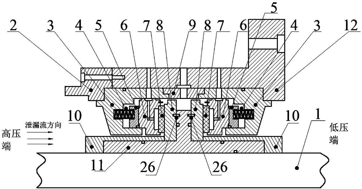
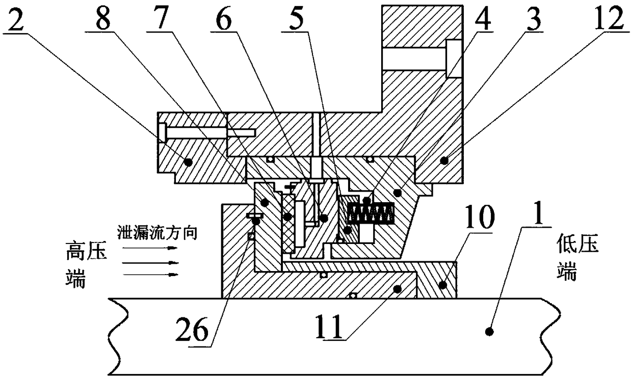
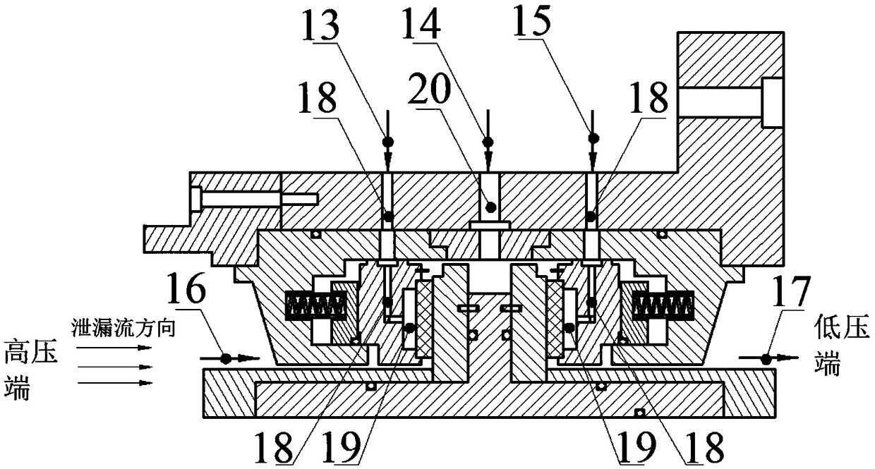
[0072] see figure 1 and figure 2 , the present invention provides a dynamic and static pressure mixed lubrication end face sealing structure, the sealing structure can adopt double end face sealing structure ( figure 1 shown) to achieve zero-leakage sealing for toxic and dangerous gases, and a single-end sealing structure is also available ( figure 2 shown) to seal the harmless process gas that allows a small amount of leakage, or to seal the ultra-high pressure process gas by axially connecting the double-end sealing structure and the single-end sealing structure.

[0073] see figure 1 and figure 2 , A dynamic and static pressure mixed lubrication end face sealing structure provided by the present invention include...


PUM


Abstract

The invention discloses a dynamic and static pressure mixing lubricating end face sealing structure which comprises a dual-end-face sealing structure, a single end face sealing structure and a seriesconnection sealing structure. The dual-end-face sealing structure feeds buffering gas to carry out zero leakage sealing on toxic and dangerous technological gas and comprises a static ring and a movable ring; the static ring has the axial degree of freedom and is provided with a lubricating gas passage, a lubricating gas pressure stabilization cavity, a porous medium friction pair and a high-precision displacement sensor and other structure; and the movable ring rotates along with a rotary shaft. Lubricating gas with adjustable pressure is fed to generate controllable gas static pressure; oneor more annular cavities penetrating through the circumferential direction are formed in the radial direction of the lubricating gas pressure stabilization cavity; the end face of the movable ring canbe a smooth end face, or a dynamic pressure groove structure is processed on the end face of the movable ring; and the groove type of the dynamic pressure groove has multiple manners including a traditional spiral groove, T-shaped groove or a novel rhombus groove structure. Under the extreme conditions including high temperature, high pressure, high rotating speed, ultralow temperature and the like, frequent start and halt and sealing of the mechanical shaft end of an impeller operating under variable working conditions can be realized.

Description

Technical field: [0001] The invention relates to a sealing structure, in particular to a non-contact gas dynamic pressure static pressure mixed lubrication end face seal used for the shaft end of a turbomachinery which can realize zero-leakage sealing. Background technique: [0002] As one of the key components of turbomachinery, the shaft end seal has a significant impact on the operating efficiency and safety of the turbomachinery due to its reliability and stability. Especially in the centrifugal compressors commonly used in the petrochemical industry, most of the process gases it transports are flammable, explosive, toxic and highly corrosive, and are usually in an ultra-high pressure and ultra-high temperature working environment. Once the seal fails, the process gas Leakage often leads to environmental pollution, fire, explosion and other major accidents. [0003] Dry gas seal is a non-contact gas lubricated mechanical seal, which is an advanced shaft end sealing tech...

Claims


Application Information

Patent Timeline
Patent Type & Authority Applications(China)
IPC IPC(8): F16J15/34
CPCF16J15/3404F16J15/3448F16J15/3452F16J15/3492
Inventor 李志刚方志李军
Owner XI AN JIAOTONG UNIV
Why Eureka
Try Eureka