Heater box

A technology for heaters and cabinets, which is applied in household heating, space heating and ventilation details, heating methods, etc. fire effect

Active Publication Date: 2018-11-06
ZHEJIANG LAISIAO ELECTRIC
View PDF11 Cites 0 Cited by
  • Summary
  • Abstract
  • Description
  • Claims
  • Application Information

AI Technical Summary

Problems solved by technology

With the improvement of living standards, people have higher and higher requirements for the appearance of various items. Due to product structure problems, large deformation of the box body during injection molding is caused, resulting in appearance defects of the main unit of the heater box body, which in turn affects people's desire to buy

Method used


Image

  • Heater box
  • Heater box
  • Heater box

Examples


Embodiment 1

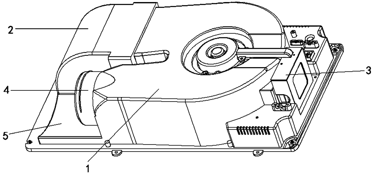
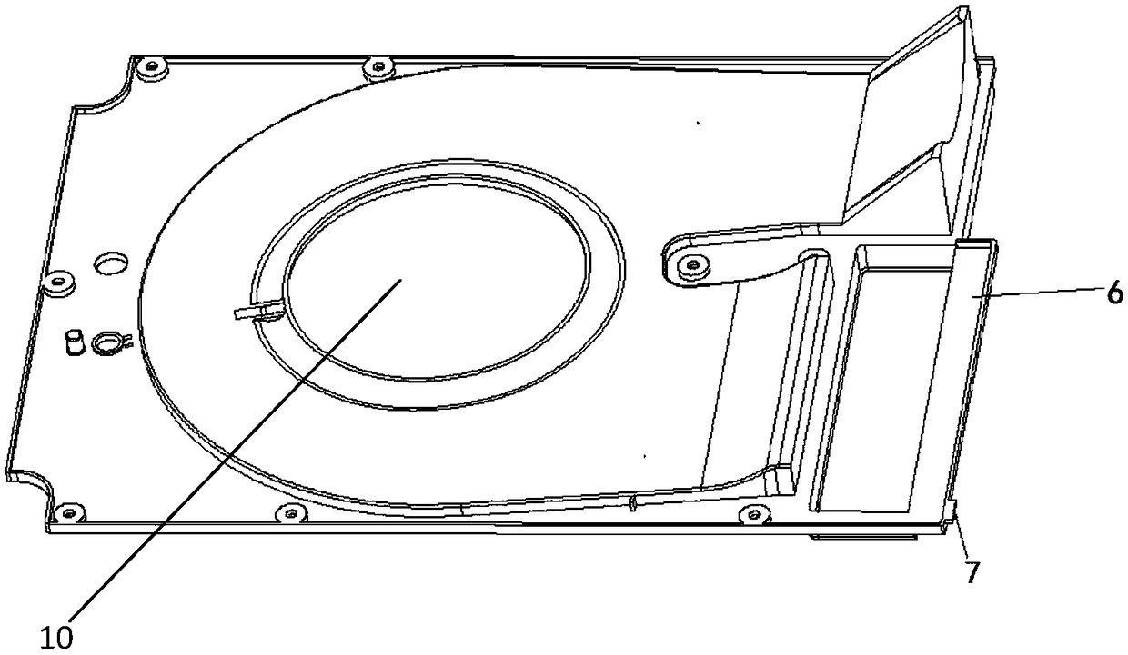
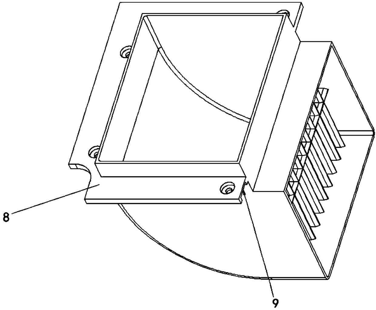
[0019] Embodiment 1: as Figure 1 to Figure 4 As shown in , a heater box includes a box body and a cover plate. There is a U-shaped groove in the middle of the box body. The U-shaped groove is covered by a cover plate to form an air duct 1. There is a One end of the air inlet duct 1 is connected to the air outlet duct 2, and the other end is a circular ventilation outlet 4. There is an arc-shaped surface 5 on the main body surface of the box below the ventilation outlet 4. The inner side of the air outlet duct 2 is right-angled, and the outer side It is arc-shaped, the rear end communicates with the air duct 1, and the front end extends outwards with a fixed surface 8, which is fixed to the front of the main body of the box, and the back of the fixed surface 8 is provided with a groove 9; Junction box 3; one end of the cover plate has a protruding clamping surface 6, and the side wall of the clamping surface 6 has clamping feet 7 extending outward, the clamping surface 6 is ag...


PUM


Abstract

A heater box comprises a box body and a cover plate. A U-shaped groove is formed in the middle of the front face of the box body and is covered with the cover plate to form an air duct. An air inlet is formed in the middle of the cover plate, one end of the air duct communicates with an air-outlet air duct, and an air-exchange air opening is formed in the other end of the air duct. The front end of the air-outlet air duct is fixed to the front face of the box body through a fixing face, and the rear end of the air-outlet air duct communicates with the air duct. The heater box is characterizedin that an arc-shaped face is arranged on the position, below the air-exchange air opening, of the surface of the box body; a groove is formed in the back face of the fixing face; an extending clamping face is arranged at one end of the cover plate, and a clamping foot is arranged on the side wall of the clamping face in an outwards extending mode; and the clamping face abuts against the air-outlet air duct, and the clamping foot is inserted into the groove in the fixing face for fixing the cover plate.

Description

technical field [0001] The present invention relates to a heater box; in particular to a heater box Background technique [0002] At present, household heaters are very common. With the improvement of living standards, people have higher and higher requirements for the appearance of various items. Due to product structure problems, large deformation of the box body during injection molding is caused, resulting in appearance defects of the main unit of the heater box body, which in turn affects people's desire to buy. Contents of the invention [0003] In order to solve the above problems, the present invention provides the following solutions: [0004] A heater box body, including a box body and a cover plate. There is a U-shaped groove in the middle of the front of the box body. The U-shaped groove is covered by the cover plate to form an air duct. The air outlet, one end of the air duct is connected with the air outlet, and the other end is the ventilation outlet. Th...

Claims


Application Information

Patent Timeline
Patent Type & Authority Applications(China)
IPC IPC(8): F24D13/00F24D19/06
CPCF24D13/00F24D19/06
Inventor 王永麟张辉姚松良
Owner ZHEJIANG LAISIAO ELECTRIC
Why Eureka
Try Eureka