
Clamping device for longitudinal arc tensile sample

A technique for tensile specimens and clamping devices, which is applied in the mechanical field to achieve the effects of ensuring uniformity, ensuring stability, and convenient clamping and operation

Pending Publication Date: 2018-11-06
CHINA INSTITUTE OF ATOMIC ENERGY
View PDF0 Cites 3 Cited by
  • Summary
  • Abstract
  • Description
  • Claims
  • Application Information

AI Technical Summary

Problems solved by technology

However, the actions of automatic auxiliary equipment are generally relatively simple, and it is difficult to perform this operation.

Method used


Image

  • Clamping device for longitudinal arc tensile sample
  • Clamping device for longitudinal arc tensile sample
  • Clamping device for longitudinal arc tensile sample

Examples


Embodiment 1

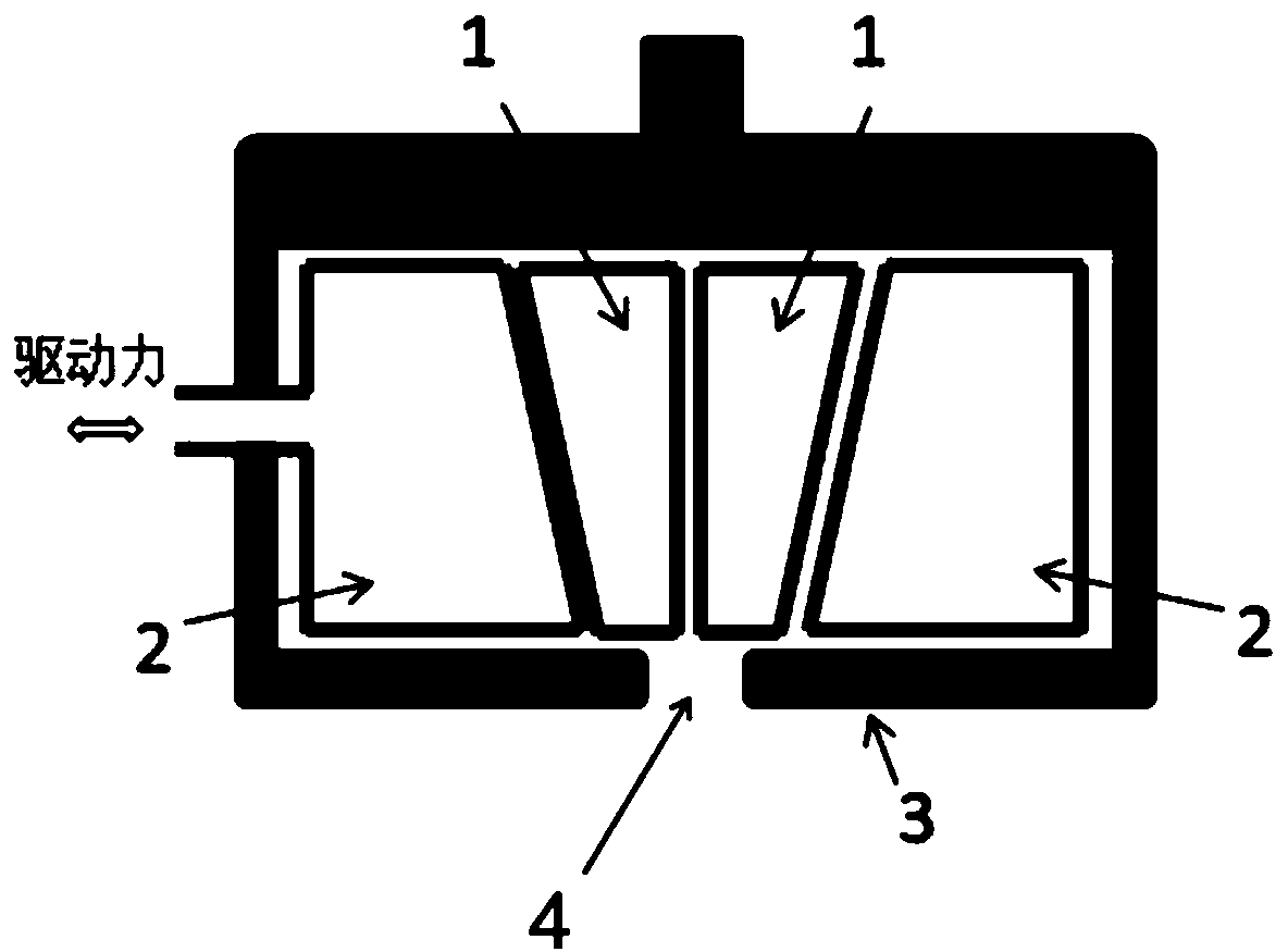
[0032] Such as figure 2 As shown, in this embodiment, the driving force of the driving mechanism is perpendicular to the clamping surface of the clamping block 1 , and only one elastic block 2 is loaded with driving force.

Embodiment 2

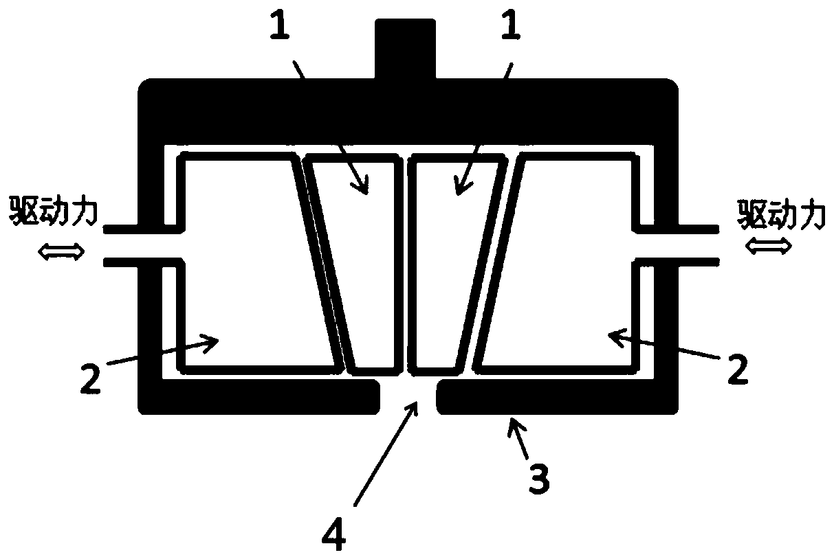
[0034] Such as image 3 As shown, in this embodiment, the driving force of the driving mechanism is perpendicular to the clamping surface of the clamping block 1 , and all the elastic blocks 2 are connected with the driving mechanism.

Embodiment 3

[0036] Such as Figure 4 As shown, in this embodiment, the outer surface of the clamping block 1 is wedge-shaped, and the elastic block 2 is provided with a wedge surface matching the outer surface of the corresponding clamping block 1; the driving force direction of the driving mechanism is not in line with the wedge face parallel. In this way, when the driving force acts on the wedge surface, a component perpendicular to the direction of the clamping surface will be generated, so as to realize the clamping function of the clamping block 1 .


PUM


Abstract

The invention relates to a clamping device for a longitudinal arc tensile sample. The clamping device comprises a clamping structure, an outer shell body and a loosening and tightening mechanism, wherein the clamping structure comprises two clamping blocks which are mutually matched, the clamping blocks and the loosening and tightening mechanism are arranged in an inner cavity of the outer shell body, the loosening and tightening mechanism can move in the outer shell body to make the clamping blocks to tightly clamp or loosen, an opening for the test sample to enter and exit the inner cavity to be matched with the clamping blocks is arranged on the outer shell body, the two clamping blocks are a convex-face clamping block and a concave-face clamping block, a convex face of the convex-faceclamping block and a concave face of the concave-face clamping block are mutually matched with each other to form an arc clamping face, and a sample pin and a pin hole which are mutually matched witheach other are respectively arranged on the convex-face clamping block and the concave-face clamping block. The clamping device has the following beneficial effects: assembling and clamping operationis convenient; in experiments, a sample only needs to be penetrated into the pin, and then fluid force or mechanical force is remotely controlled to perform loosening / clamping of the clamping blocks;the clamping device is especially suitable for poisonous and harmful sample experiments.

Description

technical field [0001] The invention relates to the mechanical field, in particular to a clamping device for a longitudinal arc tensile sample. Background technique [0002] A large number of pipes are used in nuclear reactors, such as: irradiated tunnels, process pipes, fuel cladding pipes, etc. Before and after engineering applications, these pipes need to be tested for their tensile properties after irradiation to evaluate their application performance or Aging state. The tensile performance test of the tube after irradiation usually adopts the longitudinal arc tensile specimen (such as figure 1 Shown), in order to increase the utilization rate of irradiated materials, reduce the irradiated volume and reduce radioactivity and other requirements. [0003] Tensile tests for longitudinally curved specimens require the use of special tensile fixtures to clamp the specimens to ensure the centering and stability of the tensile specimens. [0004] In the prior art, the fixtur...

Claims


Application Information

Patent Timeline
IPC IPC(8): G01N3/04G01N3/08
CPCG01N3/04G01N3/08
Inventor 钟巍华佟振峰宁广胜张长义杨文
Owner CHINA INSTITUTE OF ATOMIC ENERGY
Learn More