Heat dissipation shell of transformer

A heat dissipation shell and transformer technology, applied in transformer/inductor casing, transformer/inductor cooling, transformer/inductor components, etc., can solve the problems of high maintenance difficulty, easy dust generation, low heat dissipation efficiency, etc., to achieve Good heat dissipation effect, prevent short circuit effect

Active Publication Date: 2018-11-06
江苏星科冶金机械制造有限公司
View PDF7 Cites 2 Cited by
  • Summary
  • Abstract
  • Description
  • Claims
  • Application Information

AI Technical Summary

Problems solved by technology

[0003] The transformer is a complete set of voltage transformation equipment, which can be used for terminal power supply and ring network power supply. The conversion is very convenient and ensures the reliability and flexibility of power supply. However, the transformer will generate a lot of heat during operation. The traditional transformer heat dissipation is mainly By setting air ducts or oil ducts in the body, the heat is taken away by the circulating flow of gas or oil for heat dissipation, which is difficult to maintain and prone to dust, and is highly specific to the type of transformer and does not have universal applicability. The traditional There is also a heat sink for heat dissipation, but the heat sink is usually set inside and dissipates the heat through the ventilation holes, but the heat dissipation efficiency is not high
[0004] The traditional transformer cooling case has the following disadvantages: 1. It is easy to generate dust inside. 2. The heat sink is set inside the main casing, and the heat dissipation efficiency is low. Therefore, we introduce a transformer cooling case

Method used


Image

  • Heat dissipation shell of transformer
  • Heat dissipation shell of transformer
  • Heat dissipation shell of transformer

Examples


Embodiment Construction

[0019] The following will clearly and completely describe the technical solutions in the embodiments of the present invention with reference to the accompanying drawings in the embodiments of the present invention. Obviously, the described embodiments are only some, not all, embodiments of the present invention. Based on the embodiments of the present invention, all other embodiments obtained by persons of ordinary skill in the art without making creative efforts belong to the protection scope of the present invention.

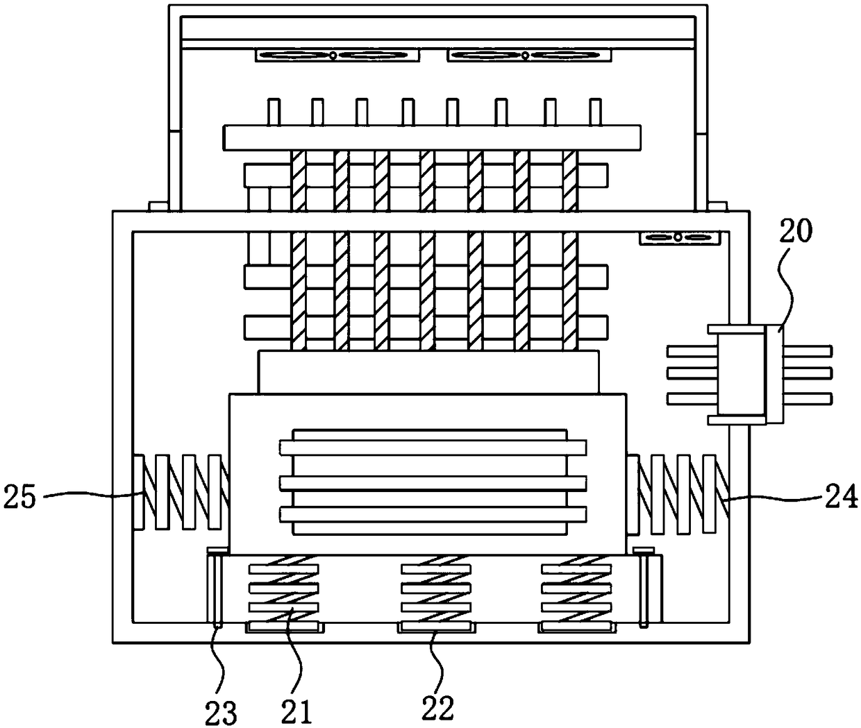
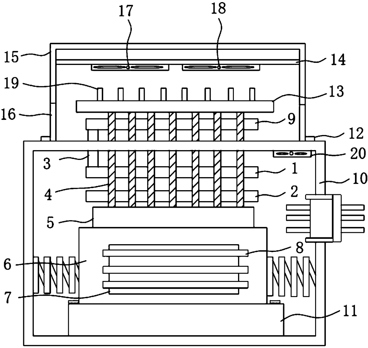
[0020] see Figure 1-3 , the present invention provides a technical solution: a transformer heat dissipation housing, including a main housing 10, a base 11 is provided inside the main housing 10, a transformer 6 is fixedly connected to the upper side of the base 11, and the The front of the transformer 6 is fixedly connected with a first copper plate 7, the first copper plate 7 is welded with a first heat dissipation aluminum sheet 8, the number of the first ...


PUM


Abstract

The invention discloses a heat dissipation shell of a transformer. The heat dissipation shell comprises a main shell, wherein a base is arranged in the main shell; the transformer is fixedly connectedto the upper side of the base; a first copper plate is fixedly connected to the front surface of the transformer; first heat dissipation aluminum sheets are welded to the first copper plate, whereinthe number of the first heat dissipation aluminum sheets is three; a second copper plate is arranged on the upper side of the transformer; and second heat dissipation aluminum sheets are welded to theupper side of the second copper plate. A part of heat generated in the working process of the transformer is subjected to heat dissipation through the second copper plate fixedly connected with the transformer; the second heat dissipation aluminum sheets are arranged on the upper part of the second copper plate, and the upper parts of the second heat dissipation aluminum sheets penetrate throughthe upper shell of the main shell, so that the upper part of the main shell is located outside the main shell, and the heat dissipation effect is better; and in addition, the main shell is in a fully-closed form, so that dust entering in the main shell is prevented, so that generation of a short circuit in the main shell due to dust entering is prevented.

Description

technical field [0001] The invention relates to the technical field of heat dissipation of transformers, in particular to a heat dissipation casing of a transformer. Background technique [0002] The transformer is a device that uses the principle of electromagnetic induction to change the AC voltage. The main components are the primary coil, the secondary coil and the iron core (magnetic core). The main functions are: voltage conversion, current conversion, impedance conversion, isolation, voltage stabilization (magnetic saturation transformer), etc. According to the use, it can be divided into: power transformers and special transformers (electric furnace transformers, rectifier transformers, power frequency test transformers, voltage regulators, mining transformers, audio transformers, intermediate frequency transformers, high frequency transformers, impact transformers, instrument transformers, electronic transformers , reactors, transformers, etc.), the heat dissipatio...

Claims


Application Information

Patent Timeline
Patent Type & Authority Applications(China)
IPC IPC(8): H01F27/02H01F27/08H01F27/22
CPCH01F27/02H01F27/025H01F27/08H01F27/085H01F27/22
Inventor 马洪军马晓娇李秀兰
Owner 江苏星科冶金机械制造有限公司
Why Eureka
Try Eureka