
Bearing bracket structure for outer rotor motor

A technology for external rotor motors and bearing brackets, which is applied in the direction of casing/cover/support, magnetic circuit shape/style/structure, electrical components, etc., and can solve the problems of motor operating life, motor errors, assembly errors, etc. that affect the service life of bearings problem, to achieve the effect of solving the impact of bearing life damage, eliminating assembly errors, and solving circular runout

Inactive Publication Date: 2018-11-06
合肥市通得力电气制造有限公司 +1
View PDF4 Cites 2 Cited by
  • Summary
  • Abstract
  • Description
  • Claims
  • Application Information

AI Technical Summary

Problems solved by technology

[0004] Now the motor has the following disadvantages: there are errors in the machining process of each part of the motor, and there are also assembly errors in the assembly of parts
Due to the errors existing in the parts and assembly process, cumulative errors will be generated after assembly. Due to the existence of cumulative errors, the bearings and shafts will run out of circles during operation, which will affect the service life of the bearings and the operating life of the motor.

Method used


Image

  • Bearing bracket structure for outer rotor motor
  • Bearing bracket structure for outer rotor motor
  • Bearing bracket structure for outer rotor motor

Examples


Embodiment Construction

[0019] The technical solutions in the embodiments of the present invention will be clearly and completely described below with reference to the accompanying drawings in the embodiments of the present invention. Obviously, the described embodiments are only a part of the embodiments of the present invention, but not all of the embodiments.

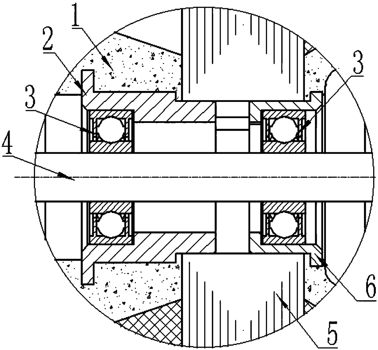
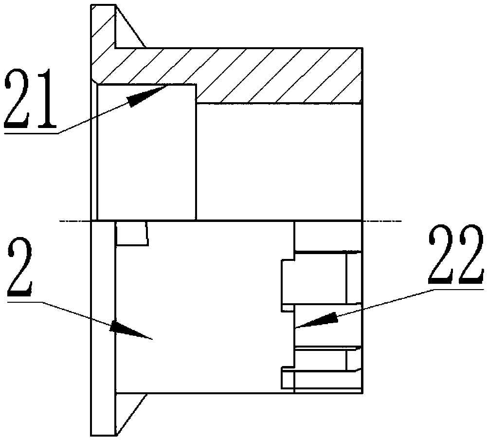
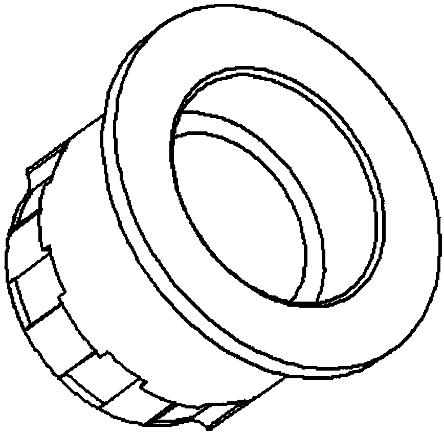
[0020] refer to Figure 1-5 , a bearing bracket structure for an outer rotor motor, comprising a stator iron core 5 and a rotating shaft 4, a first bearing bracket 2 is arranged on one side of the stator iron core 5, and a first bracket limit end is arranged at one end of the first bearing bracket 2 22. The limiting end 22 of the first bracket is coaxially fixed in the stator core 5, and the end of the first bearing bracket 2 away from the limiting end 22 of the first bracket is provided with a first bearing chamber 21, and the inside of the first bearing chamber 21 is embedded. with bearing 3;

[0021] The other side of the stator core 5 ...


PUM


Abstract

The invention relates to the technical field of the outer rotor motor, especially a bearing bracket structure for the outer rotor motor. The bearing bracket structure comprises a stator iron core anda rotating shaft; a first bearing bracket is arranged at one side of the stator iron core, a first bracket limiting end is arranged at one end of the first bearing bracket, and the first bracket limiting end is coaxially fixed in the stator iron core; a second bearing bracket is arranged at the other side of the stator iron core, a second bracket limiting end is arranged at one end of the second bearing bracket, and the second bracket limiting end is coaxially fixed in the stator iron core; a second bearing chamber is arranged in the second bearing bracket, a bearing is arranged in the secondbearing chamber, and the rotating shaft penetrates two bearings; the external of each of the first bearing bracket, the bearing, the rotating shaft, the stator iron core, and the second bearing bracket is plastic-packaged to form the stator plastic-packaged body. The bearing bracket structure disclosed by the invention effectively solves the influence of damaging the bearing life in the operationof the rotating shaft, solves the defect of circle run-out when the bearing and the rotating shaft are in operation, and effectively prolongs the service life of the motor.

Description

technical field [0001] The invention relates to the technical field of outer rotor motors, in particular to a bearing support structure for outer rotor motors. Background technique [0002] Motor refers to an electromagnetic device that realizes the conversion or transfer of electrical energy according to the law of electromagnetic induction. [0003] Plastic-encapsulated motors use plastic encapsulation technology to encapsulate the stator iron core and windings of the motor as a whole with engineering plastics, which can cancel the traditional motor stator insulation treatment process and the metal casing of ordinary motors. This micro-motor is used in household appliances such as vacuum cleaners, range hoods, air conditioners, washing machines, and instrument fans. At home and abroad, more and more attention is paid to the development and production of plastic-encapsulated motors, which have a bright future due to a series of advantages that metal-shell motors do not hav...

Claims


Application Information

Patent Timeline
Patent Type & Authority Applications(China)
IPC IPC(8): H02K5/16H02K1/18
CPCH02K5/165H02K1/187
Inventor 陶文飞张四生姚翔李剑董小振
Owner 合肥市通得力电气制造有限公司
Learn More