A Method for Determining the Instantaneous Position of Holding Roller in Special-shaped Ring Rolling

A technology of instantaneous position and special-shaped rings, applied in metal rolling, complex mathematical operations, etc., can solve problems such as complex motion control of rolling rolls and inapplicability of rolling rolls

Active Publication Date: 2019-08-09
江苏翔能科技发展有限公司
View PDF7 Cites 0 Cited by
  • Summary
  • Abstract
  • Description
  • Claims
  • Application Information

AI Technical Summary

Problems solved by technology

These studies are all aimed at the control of the movement of the rolls in the process of ring rolling with rectangular cross-sections, but the motion control of the rolls in the process of special-shaped ring rolling is relatively more complicated, so the motion control method of the rolls in the process of ring rolling with rectangular cross-sections is not applicable In profile ring rolling process

Method used


Image

  • A Method for Determining the Instantaneous Position of Holding Roller in Special-shaped Ring Rolling
  • A Method for Determining the Instantaneous Position of Holding Roller in Special-shaped Ring Rolling
  • A Method for Determining the Instantaneous Position of Holding Roller in Special-shaped Ring Rolling

Examples


Embodiment Construction

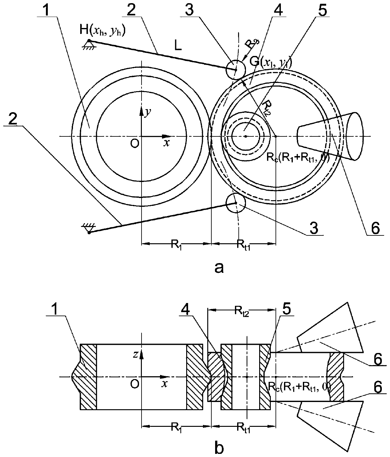
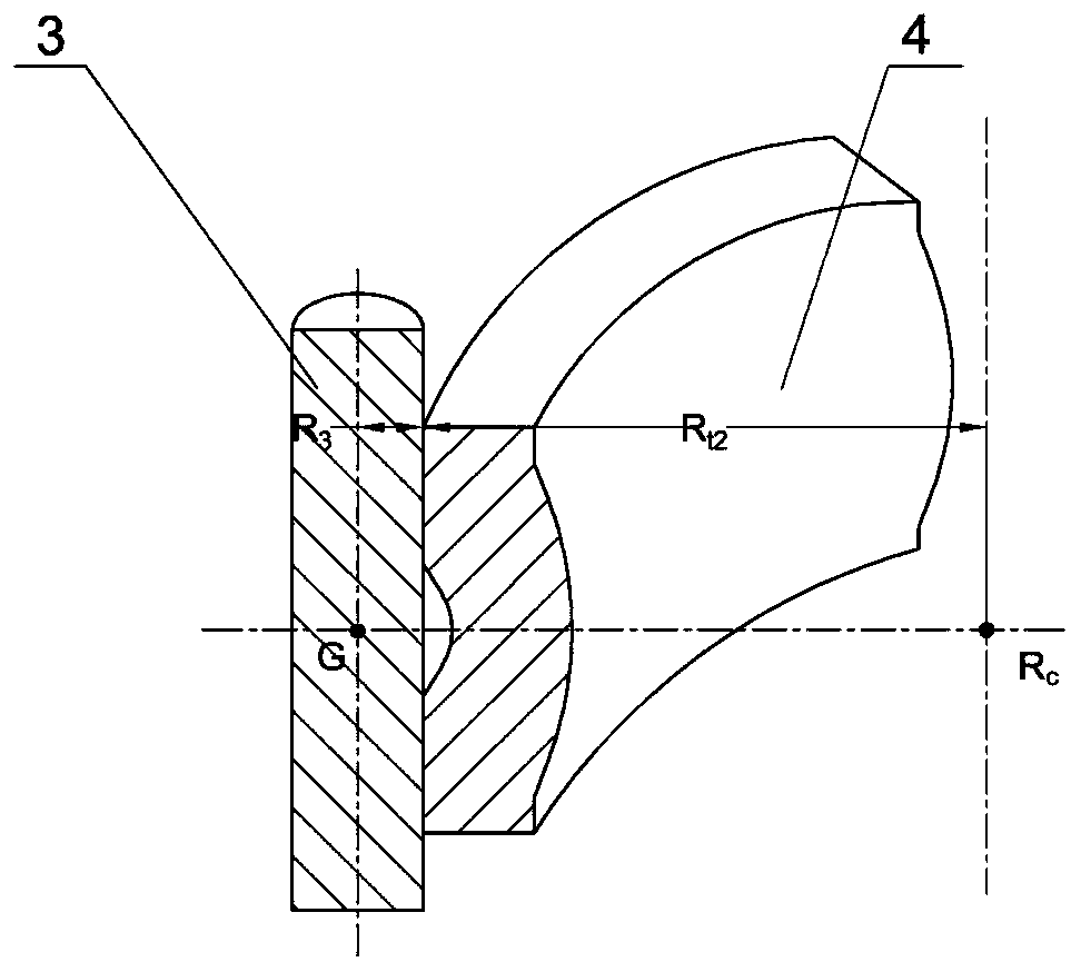
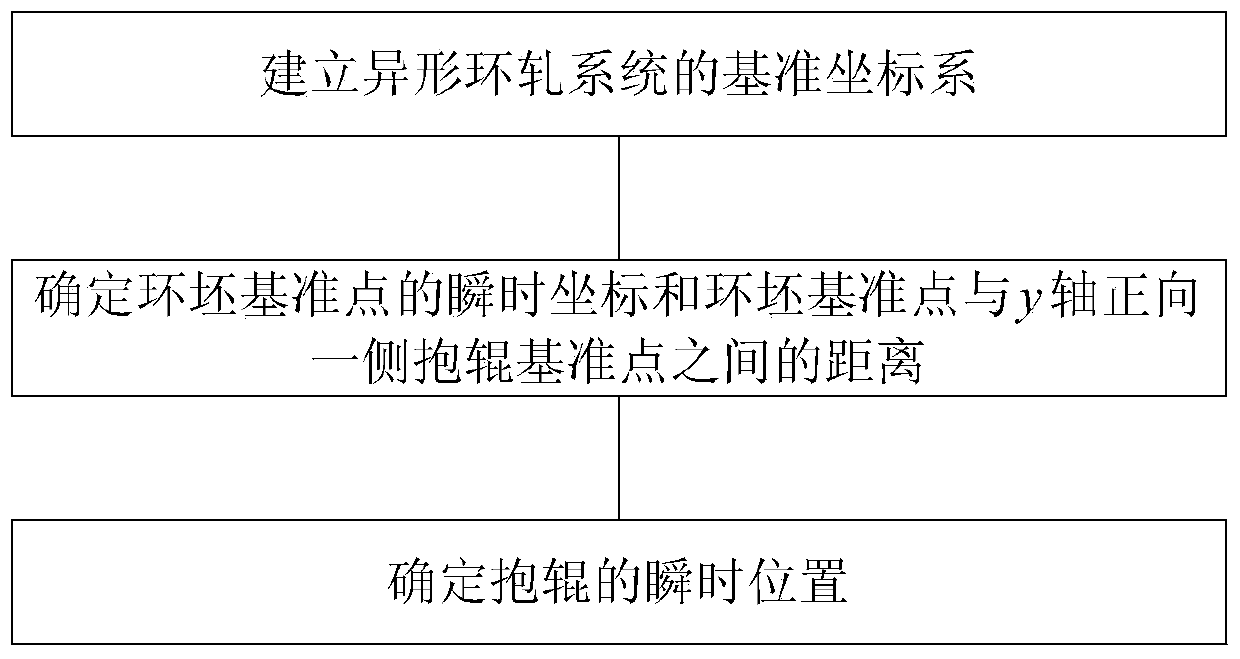
[0047] This embodiment is a method for determining the instantaneous position of the holding rolls in special-shaped ring rolling. By establishing the reference coordinate system of the special-shaped ring rolling system, the relative positional relationship between the components of the entire ring rolling system can be determined. Then determine the radii (R 1 and R 3 ) and the instantaneous radius of the ring blank at the corresponding contact (R t1 and R t2 ), to obtain the instantaneous coordinate R of the reference point of the ring blank c (R 1 +R t1 ,0) and the distance between the reference point of the ring blank and the reference point of the roll on the positive side of the y-axis (R 3 +R t2 ). Then, according to the determined relative positional relationship, list the equations about the instantaneous coordinates of the roll reference point on the positive side of the y-axis, and solve to obtain the instantaneous coordinate formula of the roll reference po...


PUM


Abstract

A method for determining an instantaneous position of a guide roller in special-shaped ring rolling includes the following steps: The method includes the following steps: establishing a reference coordinate system of a special-shaped ring rolling system to determine relative position relations among components of an entire ring rolling system, and obtaining initial coordinates of a reference pointof the guide roller on one side of a positive direction of a y-axis, fixed hinge point coordinates, and length L between the reference point of the guide roller and the fixed hinge point H; determining a radius of an earliest contact point between a main roller and the guide roller on the one side of the positive direction of the y-axis during a ring rolling process, and an instantaneous radius corresponding to a ring blank at the contact point, and obtaining instantaneous coordinates of the reference point of the ring blank, and the distance between the reference point of the ring blank andthe reference point of the guide roller on the one side of the positive direction of the y-axis; and obtaining the instantaneous coordinates of the reference point of the guide roller according to the determined relative position relations. According to the method, motion of the guide roller during the special-shaped ring rolling process can be effectively controlled, a shake of the ring blank during the rolling process is reduced, thereby reducing the offset of the reference point of the ring blank, and the stability of the special-shaped ring rolling process is improved, and the circular degree of the special-shaped ring members is improved.

Description

technical field [0001] The invention belongs to the field of rolling and forming processing of special-shaped rings, and in particular relates to a method for determining the instantaneous position of holding rolls during special-shaped ring rolling, so as to realize precise control of the movement of holding rolls during special-shaped ring rolling. Background technique [0002] During the ring rolling process, the holding rolls will move along with the growth of the ring billet and always be in contact with the ring billet to stabilize the rolling process and center the ring. very important. However, for special-shaped ring rolling, the radii of the ring blank, the main roll and the holding roll in different axial positions are different, and the contact positions of the ring blank with the main roll and the holding roll in the axial direction are different, resulting in the instantaneous coordinates of the reference point of the ring blank and the It is difficult to dete...

Claims


Application Information

Patent Timeline
Patent Type & Authority Patents(China)
IPC IPC(8): B21H1/06G06F17/12
CPCB21H1/06G06F17/12
Inventor 郭良刚李学潮
Owner 江苏翔能科技发展有限公司
Why Eureka
Try Eureka