Four-column lifting die clamping mechanism of vulcanizing machine

A vulcanizing machine and column type technology, which is applied in the field of the four-column lifting and clamping die mechanism of the vulcanizing machine, can solve the problems of low adjustment accuracy, hidden dangers, troublesome adjustment, etc. Effect

Pending Publication Date: 2018-11-09
DONGYUNINGBOHYDRAULIC MACHINE INDAL
View PDF10 Cites 0 Cited by
  • Summary
  • Abstract
  • Description
  • Claims
  • Application Information

AI Technical Summary

Problems solved by technology

Since the slide plate seat and the fixed seat are integrated, when the height of the customer’s mold changes, the clamping mechanism must first remove all the screws and the rear supporting screws and nuts, especially for large vulcanizers, the clamping mechanism itself is relatively heavy. It cannot be disassembled without the use of auxiliary equipment, and the arrangement of the machine itself is relatively compact, so it will be troublesome to adjust, it will take a lot of time, and the adjustment accuracy is not high. The clamping mechanism of the traditional column type rubber vulcanizing machine only relies on the bolt connection machine The table and the rear tooth bar support require relatively high bolt strength, especially the clamping mechanism of the large vulcanizing machine itself is relatively large, and the bolt strength requirements for the connection are too high to be guaranteed. When the vulcanizing machine is working, it is easy to loose or even Broken, there is a serious safety hazard

Method used


Image

  • Four-column lifting die clamping mechanism of vulcanizing machine
  • Four-column lifting die clamping mechanism of vulcanizing machine

Examples


Embodiment Construction

[0014] The present invention will be further described in detail below in conjunction with the accompanying drawings and specific embodiments.

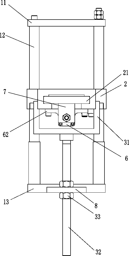
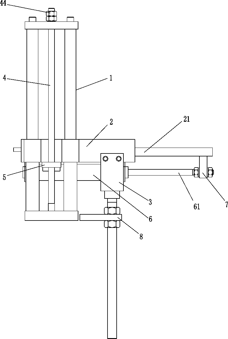
[0015] see Figure 1 to Figure 2 , a four-column lifting and clamping mechanism for a vulcanizing machine, comprising a fixed seat 1 and a sliding seat 2, the two end surfaces of the top of the fixed seat 1 and the bottom of the fixed seat 1 are respectively provided with an upper fixed plate 11 and a lower fixed plate 13, which are located on the upper Between the fixed plate 11 and the lower fixed plate 13, a tooth bar 4 and a guide pillar 12 are arranged, and the sliding seat 2 is vertically penetrated between the upper fixed plate 11 and the lower fixed plate 13 through the guide pillar 12, and the top of the tooth bar 4 Fixed with the upper fixed plate 11, the bottom end of the tooth bar 4 vertically passes through the sliding seat 2 and then connects with the lower fixed plate 13. The sliding seat 2 is provided with an adjustmen...


PUM


Abstract

The invention discloses a four-column lifting die clamping mechanism of a vulcanizing machine. The four-column lifting die clamping mechanism includes a fixed seat and a sliding seat; an upper fixingplate and a lower fixing plate are arranged on the two end faces of the top and the bottom of the fixed seat respectively, and a lead screw and a guiding pillar are arranged between the upper fixing plate and the lower fixing plate; and the sliding seat is vertically arranged between the upper fixing plate and the lower fixing plate through the guiding pillar in a penetrating mode, the top end ofthe lead screw is fixed to the upper fixing plate, the bottom end of the lead screw vertically penetrates through the sliding seat and is connected with the lower fixing plate, and an adjusting structure, a cylinder and a sliding plate capable of sliding in the axial direction are arranged on the sliding seat. The four-column lifting die clamping mechanism is simple in structure, the precise control can be achieved, meanwhile, the adjusting operation is simplified, and the adjusting efficiency is improved; and the weight of the sliding seat and the fixed seat directly acts on a machine table and is divided by adjusting a bracket, and the safety problem that the bolts are prone to loosening and breaking at the working situation that the bolts are only relied to be connected with the vulcanizing machine is successfully solved.

Description

technical field [0001] The invention relates to the technical field of rubber vulcanizing press manufacturing, in particular to a four-column lifting and clamping mechanism for a vulcanizing machine. Background technique [0002] The equipment used in the production of existing rubber products is rubber injection molding machine, which is a high-end production equipment, and the rubber products it produces are high-end products, such as automobile shock absorbers, automobile engine seals, electric insulation, etc. Manufacturing quality and product life requirements are getting higher and higher. [0003] The clamping mechanism of the traditional column type rubber vulcanizing machine adopts the integral structure of the fixed seat and the slide plate seat. The front fixed seat is connected to the table by bolts, and the rear is supported by a tooth bar. Since the slide plate seat and the fixed seat are integrated, when the height of the customer’s mold changes, the clamping...

Claims


Application Information

Patent Timeline
Patent Type & Authority Applications(China)
IPC IPC(8): B29C33/30B29C35/02
CPCB29C33/308B29C35/02
Inventor 杨桢堂舒浩梅
Owner DONGYUNINGBOHYDRAULIC MACHINE INDAL
Why Eureka
Try Eureka