Ratchet wheel control mechanism of pipe washing impoundment door

A control mechanism and pipeline flushing technology, which is applied to waterway systems, water supply devices, buildings, etc., can solve the problems of controlling the storage gate, not many, and no detailed description, etc., and achieve the effect of safe and reliable operation and low manufacturing cost

Inactive Publication Date: 2015-07-15
NANTONG VOCATIONAL COLLEGE
View PDF6 Cites 5 Cited by
  • Summary
  • Abstract
  • Description
  • Claims
  • Application Information

AI Technical Summary

Problems solved by technology

[0004] Although this kind of flushing equipment has been used at home and abroad, there are not many descriptions about the control method of the water level and the storage door. For example, the patent No. 2014200764631, the control of the storage door is through the swing cylinder and remote hydraulic operation. The system controls the water level and the storage door, which belongs to electrical control. Although the control of the storage door can be effectively realized, its control requires external power resources and manual operation
[0005] In addition, such as the patent No. 201310052117X, it describes a kind of unpowered storage door, which controls the water level through the buoy, and uses the connecting rod to trigger the actuator to control the opening and closing of the storage door, but its manual only describes its actuator. The core is the hydraulic storage, and the rest of the mechanisms are not described. Therefore, in the patent, how the connecting rod triggers the actuator and how to control the storage door is not described in detail. This makes it impossible for technicians to truly control the storage door through the water level.

Method used


Image

  • Ratchet wheel control mechanism of pipe washing impoundment door
  • Ratchet wheel control mechanism of pipe washing impoundment door
  • Ratchet wheel control mechanism of pipe washing impoundment door

Examples


Embodiment Construction

[0025] The technical solutions of the embodiments of the present invention will be clearly and completely described below in conjunction with the accompanying drawings of the present invention.

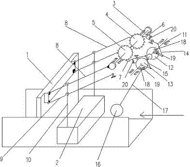
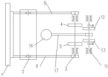
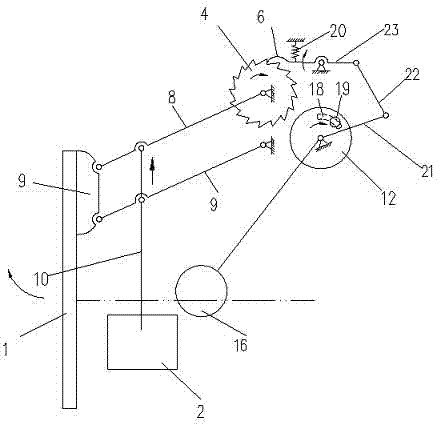
[0026] Such as Figure 1~4 As shown, a ratchet control mechanism for pipeline flushing storage door disclosed by the present invention controls the storage door through a purely mechanical ratchet control mechanism. The specific structure includes a storage door 1, a buoy 2, a water level adjustment control mechanism and a storage door control mechanism.

[0027] The shape of the storage door 1 is consistent with the cross-sectional shape of the drainage pipe, and a sealing strip is installed around it, so that the storage door is in sealing contact with the side wall of the sewage pipe to prevent leakage of the water storage.

[0028] Wherein said water level adjustment control mechanism comprises a second shaft 11, a first adjusting disc 12, a second adjusting disc 13, a first link...


PUM


Abstract

The invention discloses a ratchet wheel control mechanism of a pipe washing impoundment door. The ratchet wheel control mechanism comprises the impoundment door, a floating barrel, a water level adjusting mechanism and an impoundment door control mechanism. The impoundment door is connected with the impoundment door control mechanism through two parallel first support connecting rods, and the floating barrel is connected with the first support connecting rods and second support connecting rods through two parallel suspenders. The water level adjusting mechanism drives the impoundment door control mechanism through floating force of the water level during rising and dropping. According to the ratchet wheel control mechanism of the pipe washing impoundment door, the impoundment door is controlled through the pure mechanical ratchet wheel control mechanism, and the floating force of water serves as driving force to be used in cooperation with the ratchet wheel control mechanism to achieve the no-man control blocking-water storage-pipe washing process on a blow-off line. in addition, compared with electric control, the manufacturing cost of the ratchet wheel control mechanism is low, operation is safe and reliable, manual operation is not needed, and outside input energy resources are not needed.

Description

technical field [0001] The invention relates to a control mechanism of a storage door, in particular to a ratchet control mechanism of a storage door which realizes regular flushing of sewage pipes. Background technique [0002] In the existing urban sewage system, whether it is separate sewage discharge or combined sewage discharge, there will be sedimentation of pollutants in the sewage pipes, which requires regular cleaning of the sewage pipes. [0003] The pipeline flushing and storage door is a mechanical device used for regular flushing of the sewage pipeline, which can automatically flush the sewage pipeline regularly. Its working principle is to intercept the water in the sewage pipeline through the storage gate, so as to realize water storage. When the water level reaches a certain height, the storage door is opened, and a large amount of water rushes out from the open storage door to form a shock flow, thereby flushing the lower pipeline. After the water level drop...

Claims


Application Information

Patent Timeline
Patent Type & Authority Applications(China)
IPC IPC(8): E03F7/02
Inventor 张丽萍
Owner NANTONG VOCATIONAL COLLEGE
Why Eureka
Try Eureka