
Porous strip thread binding machine and porous strip thread binding method

A technology of a perforated belt and a binding machine, applied in the direction of binding, etc., can solve the problems of low production efficiency, can not meet the fast binding of large-capacity work, etc., and achieve the effect of simple operation

Inactive Publication Date: 2018-11-09
ZHONGCHAUNGEN TIANJIN TECH CO LTD
View PDF0 Cites 9 Cited by
  • Summary
  • Abstract
  • Description
  • Claims
  • Application Information

AI Technical Summary

Problems solved by technology

[0005] The object of the present invention is to provide a kind of perforated belt thread binding machine, to solve existing in the prior art, the perforated belt thread binding drilling and hook line need to be drilled one by one, the production efficiency is low, can not meet the fast binding of large-capacity work technical problem
[0006] The purpose of the present invention is to provide a kind of perforated strip line binding method, to solve the technical problems existing in the prior art, the drilling and hooking lines of the binding machine are all completed one by one, and the production efficiency is low.

Method used

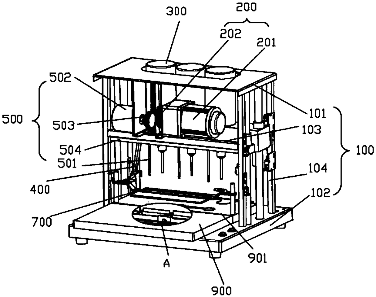
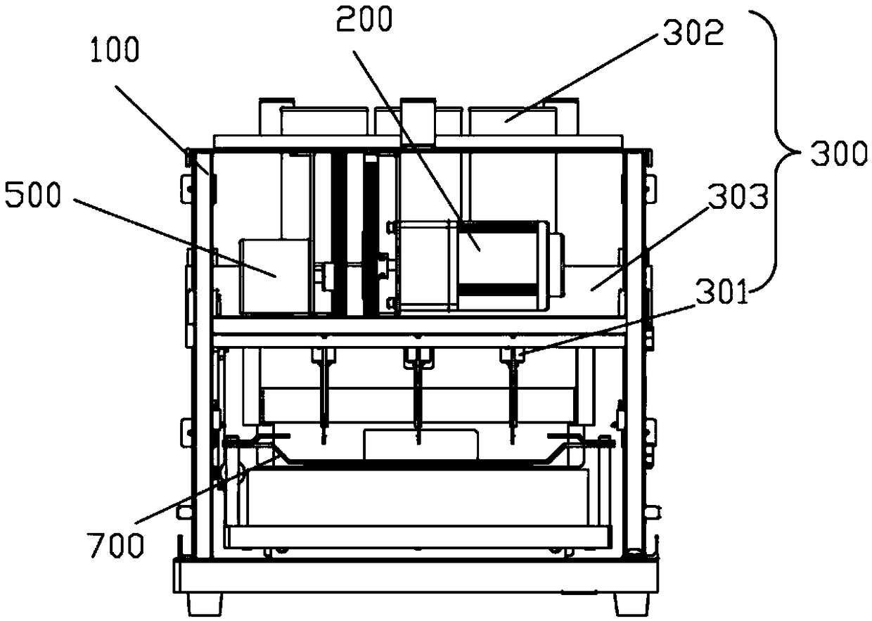
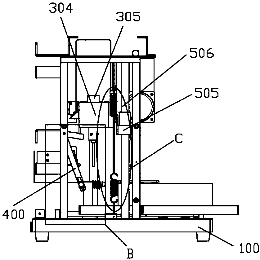

Image

  • Porous strip thread binding machine and porous strip thread binding method
  • Porous strip thread binding machine and porous strip thread binding method
  • Porous strip thread binding machine and porous strip thread binding method

Examples


Embodiment Construction

[0046] The technical solutions of the present invention will be clearly and completely described below in conjunction with the accompanying drawings. Apparently, the described embodiments are some of the embodiments of the present invention, but not all of them. Based on the embodiments of the present invention, all other embodiments obtained by persons of ordinary skill in the art without making creative efforts belong to the protection scope of the present invention.

[0047] In the description of the present invention, it should be noted that if the terms "center", "upper", "lower", "left", "right", "vertical", "horizontal", "inner", "outer" appear ” and other indicated orientations or positional relationships are based on the orientations or positional relationships shown in the accompanying drawings, which are only for the convenience of describing the present invention and simplifying the description, rather than indicating or implying that the referred device or element ...


PUM


Abstract

The invention provides a porous strip thread binding machine and a porous strip thread binding method, relating to the technical field of binding equipment. The porous strip thread binding machine comprises a support frame, a lifting mechanism, a drilling mechanism, a ranging abdication mechanism, a thread hooking mechanism, a thread feeding mechanism and a sliding table, wherein one surface of the sliding table is in contact with a sliding table frame plate, and the other surface of the sliding table is used for placing to-be-bound objects; the thread hooking mechanism and the supporting mechanism are connected with the support frame, the thread hooking mechanism and the drilling mechanism are arranged in parallel, and the lifting mechanism is connected with the drilling mechanism; the ranging abdication mechanism is arranged on the side surface of the support frame, one end of the ranging abdication mechanism is connected with the drilling mechanism, and the other end of the rangingabdication mechanism is connected with the sliding table; hooking needles are arranged at a thread hooking end of the thread hooking mechanism; the thread feeding mechanism is connected with the baseplate of the support frame, and a groove for placing cotton threads is formed in the sliding table; and multiple hooking needles and drilling tools are arranged. According to the porous strip thread binding machine, the technical problem of low binding production efficiency in the prior art is solved. The porous strip thread binding machine is controlled by virtue of a hooking needle driving mechanism and a drilling driving mechanism, so that the machining efficiency is high.

Description

technical field [0001] The invention relates to the technical field of binding equipment, in particular to a porous strip line binding machine and a porous strip line binding method. Background technique [0002] By binding paper, plastic, leather, etc. with staples or hot-melt adhesives, cotton threads, nylon tubes, etc., the binding and collection of documents, account books, account books, and bills is realized, and it is convenient for all walks of life to collect different types of documents. tidy. The traditional manual thread binding method is to use a thread awl to pierce small holes and then hook the binding thread one by one with a crochet needle, and finally tie a knot and bind it by hand. During the binding process, it is necessary to forcefully puncture the binding object, which is not only time-consuming but also labor-intensive, inefficient, and the binding thickness is also relatively limited. [0003] With the development of science and technology, electri...

Claims


Application Information

Patent Timeline
Patent Type & Authority Applications(China)
IPC IPC(8): B42B2/04
CPCB42B2/04Y02W30/66
Inventor 李娟
Owner ZHONGCHAUNGEN TIANJIN TECH CO LTD
Learn More