
Ball valve with valve body self-sealing mechanism

A self-sealing, valve body technology, applied in the valve shell structure, valve operation/release device, valve details, etc., to achieve the effect of expanding the scope of use scenarios

Pending Publication Date: 2018-11-09
TANGGONG VALVE GRP CO LTD
View PDF1 Cites 0 Cited by
  • Summary
  • Abstract
  • Description
  • Claims
  • Application Information

AI Technical Summary

Problems solved by technology

However, the sides of the gasket of this kind of ball valve except the sealing surface are all interference fit in the installation groove, and are not in direct contact with the fluid in the accommodating cavity, resulting in the gasket not being able to achieve self-sealing according to the pressure in the cavity, which needs to be improved

Method used


Image

  • Ball valve with valve body self-sealing mechanism
  • Ball valve with valve body self-sealing mechanism
  • Ball valve with valve body self-sealing mechanism

Examples


Embodiment 1

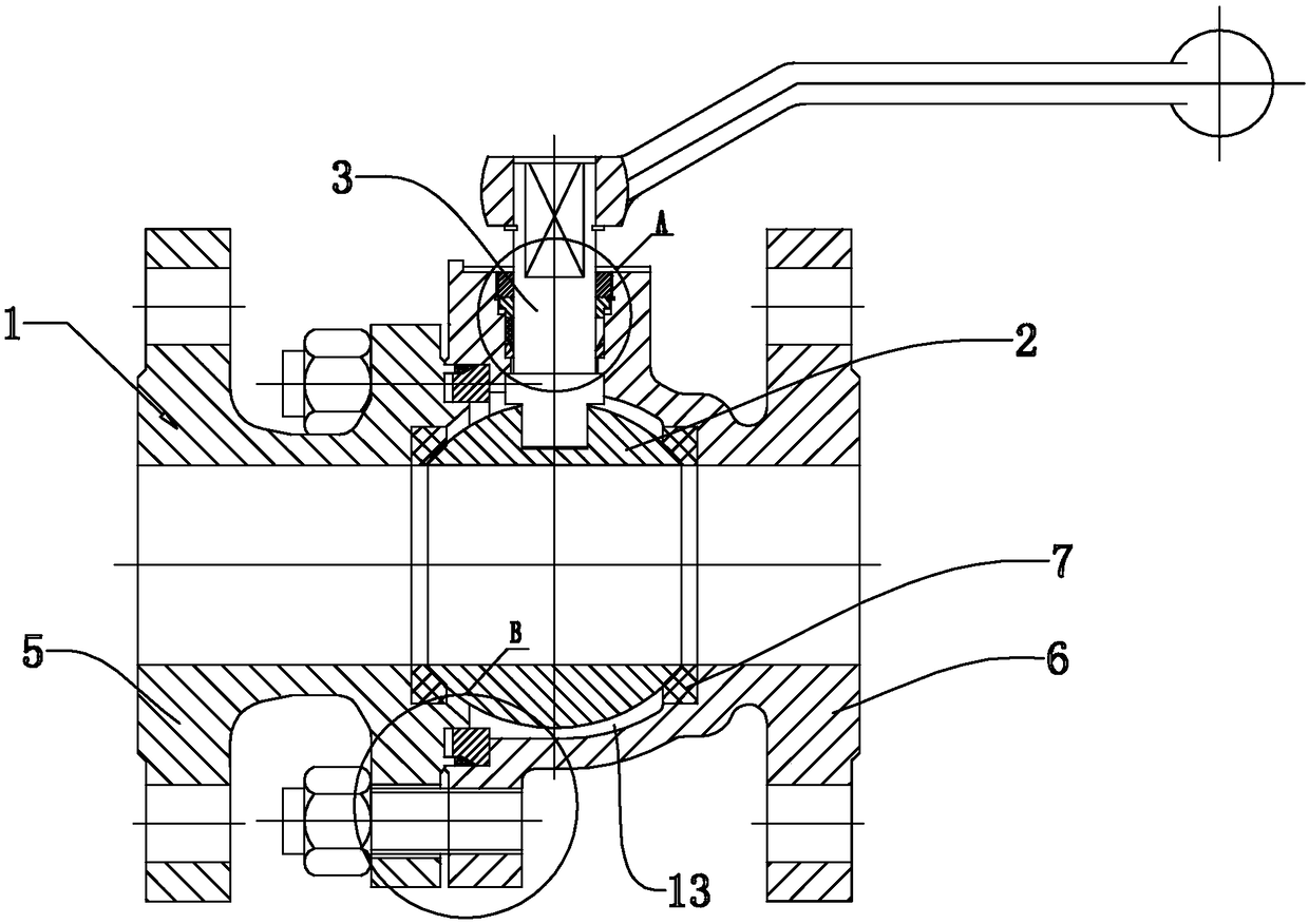
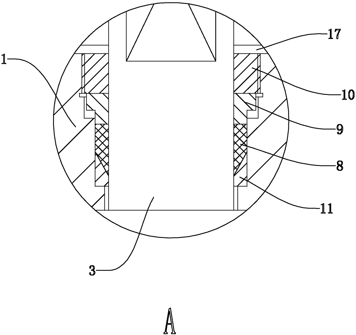
[0027] Such as figure 1 with figure 2 As shown, a ball valve with a valve body self-sealing mechanism includes a valve body 1, a ball 2, a valve stem 3 and a drive unit for driving the valve stem 3, and the valve body 1 is fixedly connected by a left valve body 5 and a right valve body 6 Formed, the valve body 1 is provided with a valve seat 7 . The valve body 1 is provided with an accommodating cavity 13 , and the ball 2 is placed in the accommodating cavity 13 . A first molding packing 8 is arranged between the valve body 1 and the valve stem 3, and a packing gland 9 for pressing the first molding packing 8 is arranged above the first molding packing 8, and the packing gland 9 is far away from the first molding packing 8. One side is provided with an adjusting nut 10 that drives the packing gland 9 to perform the operation of compressing the first molding packing 8; for the slope.

[0028] When the pressure in the accommodating chamber 13 is low pressure, the gland move...

Embodiment 2

[0036] Such as Figure 4 , Figure 5 with Image 6 As shown, the difference from the first embodiment is that the gasket 16 includes a metal skeleton 18 and a rubber sealing body 19 that can cover the metal skeleton 18 . Both the metal skeleton 18 and the rubber sealing body 19 are ring-shaped, and the metal skeleton 18 can improve the structural strength of the rubber sealing body 19, making the rubber sealing body 19 suitable for different pressure requirements and pressure environments, so as to expand the range of use scenarios.

[0037] The side of the rubber sealing body 19 close to the left valve body 5 is provided with two parallel outer sealing lips 20 , and the two outer sealing lips 20 are respectively aligned with the two end surfaces of the rubber sealing body 19 . A groove 21 is formed between the two outer sealing lips 20, and grease is applied in the groove 21. Since the rubber sealing body 19 will move in the slideway 12 under the high pressure environment,...


PUM


Abstract

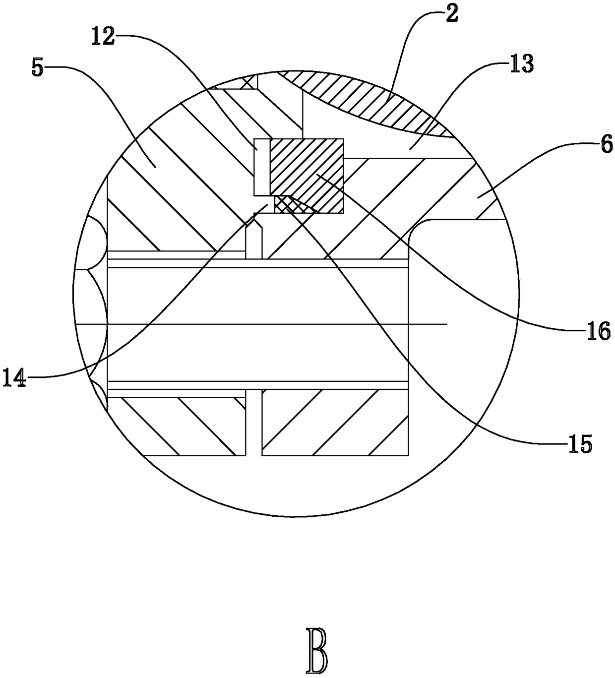
The invention discloses a ball valve with a valve body self-sealing mechanism. The ball valve with the valve body self-sealing mechanism comprises a valve body, a sphere body, a valve rod and a driveunit for driving the valve rod. The valve body is formed by fixedly connecting a left valve body and a right valve body; a valve seat is arranged in the valve body; a holding cavity is arranged on thevalve body; the sphere body is arranged in the holding cavity; a slideway is arranged between the left valve body and the right valve body; one side of the slideway communicates with the holding cavity; a positioning step fixedly connected with the left valve body is built in the slideway; a second forming filler is arranged at the position, in the slideway, on one side of the positioning step; asealing pad capable of moving in the slideway is arranged on one side of the second forming filler; and an abutting inclined surface for enabling the sealing pad and the second forming filler to contact is arranged between the sealing pad and the second forming filler. The ball valve with the valve body self-sealing mechanism provided by the invention has the following beneficial effects that thesealing pad in the ball valve communicates with the holding cavity, so that self-sealing can be realized according to the pressure size in the cavity, and a sealing effect of the connecting part of the left valve body and the right valve body is improved.

Description

technical field [0001] The invention relates to a ball valve, in particular to a ball valve with a valve body self-sealing mechanism. Background technique [0002] At present, ball valves are widely used in petroleum refining, long-distance pipelines, chemical industry, papermaking, pharmaceuticals, water conservancy, electric power, municipal, steel and other industries, and occupy a pivotal position in the national economy. It has the action of rotating 90 degrees. The cock body is a sphere with a circular through hole or channel passing through its axis. [0003] The Chinese patent with the notification number CN203009892U discloses a split ball valve. The ball valve includes a valve body, a ball, a valve stem and a drive unit for driving the valve stem. The valve body is fixedly connected by a left valve body and a right valve body. The ball is close to There is a groove on the end surface of the valve stem, the lower end of the valve stem is fixed in the groove, the va...

Claims


Application Information

Patent Timeline
Patent Type & Authority Applications(China)
IPC IPC(8): F16K5/06F16K5/08F16K27/06F16K31/60
CPCF16K5/0663F16K5/08F16K27/067F16K31/60
Inventor 项策陈永刚汪德维曾清水
Owner TANGGONG VALVE GRP CO LTD
Learn More