Novel desert photovoltaic power station technology

A photovoltaic power station and desert technology, applied in the direction of photovoltaic power generation, photovoltaic modules, photovoltaic module support structures, etc., can solve problems such as complex operation process and potential safety hazards, achieve high degree of automation, improve practicability, increase ease of operation and safety effect

Inactive Publication Date: 2018-11-09
宁波智正伟盈信息科技有限公司
4 Cites 0 Cited by

AI-Extracted Technical Summary

Problems solved by technology

[0002] With the continuous development of science and technology, more and more desert power stations have been put into use. Desert power stations mainly rely on photovoltaic power generation to supply power to some larger electr...

Abstract

The invention discloses a novel desert photovoltaic power station technology, which comprises an electrifying device and a photovoltaic device, wherein the electrifying device is arranged inside a base body; the photovoltaic device is arranged above the base body; the electrifying device comprises a first slide connection cavity arranged in the base body and a first transfer connection cavity arranged in the base body positioned at the right side of the first slide connection cavity; a second slide connection cavity is formed in the inner top wall of the first slide connection cavity; an electrifying head is arranged in the first slide connection cavity in a slide connection way; a first inclined angle block fixedly connected with the top of the electrifying head is arranged in the secondslide connection cavity in a slide connection way; a third slide connection cavity is formed in the inner bottom wall of the first slide connection cavity; a slide connection block fixedly connected with the bottom of the electrifying head is glidingly arranged in the third slide connection cavity.

Application Domain

Photovoltaic supportsCoupling device details +1

Technology Topic

Photovoltaic power stationElectrical and Electronics engineering +2

Image

  • Novel desert photovoltaic power station technology

Examples

  • Experimental program(1)

Example Embodiment

[0018] All the features disclosed in this specification, or all disclosed methods or steps in the process, except for mutually exclusive features and/or steps, can be combined in any manner.
[0019] Any feature disclosed in this specification (including any appended claims, abstract and drawings), unless specifically stated, can be replaced by other equivalent or alternative features with similar purposes. That is, unless otherwise stated, each feature is just one example of a series of equivalent or similar features.
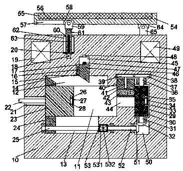
[0020] Such as figure 1 As shown, a new type of desert photovoltaic power station technology of the device of the present invention includes a base 10, a power connection device disposed inside the base 10, and a photovoltaic device disposed above the base 10, and the power connection device includes The first sliding connection cavity 11 in the base body 10 and the first transition cavity 29 in the base body 10 disposed on the right side of the first sliding connection cavity 11, the inner top wall of the first sliding connection cavity 11 is provided with a Two sliding connection cavities 11, the first sliding connection cavity 11 is slidably installed with a power connector 23, and the second sliding connection cavity 12 is slidably installed with a first bevel block fixedly connected to the top of the power connection 23 14. The inner bottom wall of the first sliding connection cavity 11 is provided with a third sliding connection cavity 13, and a sliding connection block 24 fixedly connected to the bottom of the power connection head 23 is slidably arranged in the third sliding connection cavity 13. The connecting block 24 is provided with a first screw hole, and a first screw rod 13 is fitted in the first screw hole. The left end of the first screw rod 13 is rotatably disposed on the third In the inner wall of the left side of the sliding connection cavity 13, and the right end is dynamically connected to the left end surface of the first electric transfer machine 53, the first electric transfer machine 53 is fixedly arranged in the right inner wall of the third sliding connection cavity 13, and the first The outer side of the electric transfer machine 53 is provided with a supporting component, the supporting component includes a shock-reducing composite plate 531 and a cooling iron sheet 532, and a fourth sliding contact cavity 11 is connected to the first adapter cavity 29. In the sliding connection cavity 44, the first adapter cavity 29 is rotatably provided with an adapter cylinder 30, and the inner top wall of the first adapter cavity 29 is provided with a first mounting groove 38 extending left and right. The inner bottom wall of the adapter cavity 29 is colored and has a second mounting groove 50. A first adapter shaft 36 is rotatably arranged between the first mounting groove 38 and the first adapter cavity 29. The top of the first adapter shaft 36 extends into the first mounting groove 38 and a first gear wheel 37 is fixed at the tail of the top. The bottom of the first adapter shaft 36 extends into the first adapter cavity 29 And is fixedly connected to the top end surface of the adapter cylinder 30, a second adapter shaft 31 is rotatably arranged between the second mounting groove 50 and the first adapter cavity 29, and the second rotation The top of the connecting shaft 31 extends into the first adapter cavity 29 and the top tail is fixedly connected to the bottom end surface of the adapter cylinder 30, and the bottom of the second adapter shaft 31 extends into the second mounting groove 50 And the bottom tail is fixedly provided with a first bevel wheel 32, the left inner wall of the second mounting groove 50 is rotatably provided with a second bevel wheel 51 that is matedly connected with the first bevel wheel 32, and the second bevel wheel The left end surface of the wheel 51 is fixedly provided with a third adapter shaft 52 which is dynamically connected to the right end surface of the first electric rotary machine 53, and a sliding connection table 40 is installed in the fourth sliding connection cavity 44 which can be connected up and down, The inner bottom of the sliding joint 40 is provided with a first communicating groove 42 penetrating left and right. The first communicating groove 42 is fixedly provided with a conductive block 43. The top end of the sliding joint 40 is provided with an upward mouth. The second screw-shaped hole is fitted with a second screw-shaped rod 41, the top of the second screw-shaped rod 41 extends into the first mounting groove 38 and the top tail The portion is fixedly provided with a second gear wheel 38 matingly connected with the first gear wheel 37.
[0021] Beneficially or illustratively, the photovoltaic device includes a frame 54 arranged above the top of the base 10 and a fifth sliding contact cavity 60 arranged on the left side of the top end surface of the base 10 with the mouth upward. A mounting cavity is provided in the top end surface of the frame body 54 in which a photovoltaic panel 56 is fixed. The bottom end surface of the frame body 54 is provided with a dovetail groove 57 with a downward mouth, and the dovetail groove 57 slides in the middle. A dovetail block 58 is slidably installed in the fifth sliding connection cavity 60, and a sliding connection rod 61 is slidingly installed in the fifth sliding connection cavity 60. The sliding rod 61 is provided with a third screw-shaped hole whose mouth is downward, and a third screw-shaped rod 53 is fitted in the third screw-shaped hole. The bottom of the third screw-shaped rod 53 is fixedly arranged at The second electric rotary machine 18 in the inner bottom wall of the fifth sliding connection cavity 60 is dynamically connected, and first guide grooves 62 are symmetrically provided in the left and right inner walls of the fifth sliding connection cavity 60, and the first guide grooves 62 slide in A first guide block 20 fixedly connected to the sliding rod 61 is installed, a second fixing block 64 is fixed on the right side of the bottom end surface of the frame body 54, and a second fixing block 64 is fixed on the right side of the top end surface of the base body 10 The connecting arm 65 is hingedly mounted on the second fixing block 64.
[0022] Beneficially or illustratively, the inner top of the base 10 is respectively fixedly provided with a storage battery 19 located on the left side of the fifth sliding contact cavity 60 and an inverter 49 located on the right side of the fifth sliding contact cavity 60, and the photovoltaic The board 56, the inverter 49, and the battery 19 are connected in series.
[0023] Advantageously or illustratively, the inner top wall of the second sliding connection cavity 14 is provided with an upwardly elongated sixth sliding connection cavity 45, and the inner top wall of the sixth sliding connection cavity 45 is provided with an electrical connection with the battery 19 The power supply slot 48 in the sixth sliding connection cavity 45 is slidably installed with a second bevel block 46 that is matched with the first bevel block 14. The bottom of the second bevel block 46 is provided with the The power supply piece 47 is matched with the power supply groove 48. A second guide groove 17 is provided in the left inner wall of the sixth sliding connection cavity 45. The second guide groove 17 is slidably mounted with the second oblique angle The second guide block 15 is fixedly connected to the block 46, and the inner top wall of the second guide groove 17 is provided with an elastic piece 16 that abuts against the second guide block 15.
[0024] Beneficially or illustratively, wherein the right side end surface of the adapter cylinder 30 is provided with a first concave groove 35 with a rightward mouth, and the first concave groove 35 is elastically installed in the first elastic member 33 There is a first conductive sheet 34 electrically connected to the power supply sheet 47.
[0025] Beneficially or exemplarily, wherein the right side end surface of the power connector 23 is provided with a second concave groove 26 with the mouth facing right, and the second concave groove 26 is elastically installed in the second elastic member 28 There is a second conductive sheet 27. The left end wall of the first sliding contact cavity 11 is provided with a second communicating groove 21 communicating with the outside, and one end of the second communicating groove 21 is slidably mounted with the second communicating groove 21. The conductive sheet 27 is electrically connected, and the other end is electrically connected to the power cord 22 of the electrical equipment.
[0026] Beneficially or exemplarily, the vibration reduction composite plate 531 is arranged at the upper end and the lower end of the first electric converter 53 and is fixedly connected to the first electric converter 53, and the cooling iron sheet 532 is arranged at the The front and rear ends of the first electric transfer machine 53 are fixedly connected to the housing of the first electric transfer machine 53, the upper and lower ends of the cooling iron sheet 532 are fixedly connected to the vibration reduction composite board 531, and the At the front end and the rear end of an electric converter 53 are respectively provided with more than one cooling iron sheet 532. The cooling iron sheet 532 is used to absorb and dissipate the heat generated during the operation of the first electric converter 53. The composite board 531 is used to reduce the vibration force generated by the first electrical converter 53 during operation, and prevent excessive vibration force from affecting the normal operation of the device.
[0027] When the device of the present invention is in the initial state, the left end face of the electrical connection head 23 abuts against the left end wall of the first sliding contact cavity 11. Under the action of the elastic piece 16, the bottom of the second bevel block 46 extends Into the second sliding connection cavity 12, the top end surface of the sliding connection platform 40 abuts against the inner top wall of the fourth sliding connection cavity 44.
[0028] When in use, control the rotation of the first electroconverter 53. The rotation of the first electroconverter 53 can simultaneously control the rotation of the first screw rod 25 and the third adapter shaft 52, and the first screw rod 25 can rotate. Then, the sliding block 24 can be driven to drive the electrical connection head 23 and the first bevel block 14 to slide to the right, and at the same time, the third adapter shaft 52 can pass through the second The bevel wheel 51 drives the first bevel wheel 32 to drive the second adapter shaft 31, the adapter cylinder 30, the first adapter shaft 36, the first gear wheel 37, the second gear wheel 39, and the second screw The rod 41 rotates. After the second screw rod 41 rotates, the sliding table 40 can be driven to slide downward. When the right end surface of the electrical connection head 23 abuts against the right inner wall of the first sliding cavity 11 , The adapter cylinder 30 rotates 180 degrees, the left and right sides of the conductive block 43 abut against the second conductive sheet 27 and the first conductive sheet 34, and then the electrical connection head 23 slides to the right During the process, the first bevel block 14 can act on the second bevel block 46 to slide upward, so that the power supply sheet 47 is inserted into the power supply slot 48, thereby enabling the power cord 22 to be charged. And realize the power supply operation of the electric equipment;
[0029] After the power supply is completed, the device of the present invention can be restored to the initial state by controlling the reverse rotation of the first electric converter 53;
[0030] When the angle of the photovoltaic panel 56 needs to be adjusted, the device of the present invention controls the rotation of the second electroconverter 18, and after the second electroconverter 18 rotates, the third screw rod 63 can drive the sliding joint. The rod 61 slides upwards, so that one end of the frame body 54 can be pressed upwards, so that the angle adjustment of the photovoltaic panel 56 can be realized. When the angle adjustment is completed, the second electroconverter 18 can be controlled to stop rotating. .
[0031] The beneficial effects of the present invention are:
[0032] When the device of the present invention is in use, it controls the rotation of the first electroconverter. The rotation of the first electroconverter can simultaneously control the rotation of the first screw rod and the third adapter shaft. After the first screw rod rotates, The sliding block can be driven to drive the electrical connection head and the first bevel block to slide to the right, and at the same time, the third adapter shaft can drive the second cone wheel after rotating The first bevel wheel drives the second adapter shaft, the adapter cylinder, the first adapter shaft, the first gear wheel, the second gear wheel, and the second screw rod to rotate, and the second screw rod rotates Then, the sliding connection table can be driven to slide downward. When the right end surface of the power connection head abuts against the right inner wall of the first sliding connection cavity, the degree of rotation of the adapter cylinder, the left and right end surfaces of the conductive block Respectively abut the second conductive sheet and the first conductive sheet, and during the rightward sliding process of the electrical connector, the first bevel block can act on the second bevel block to slide upward, The power supply sheet is inserted into the power supply slot, so that the power cord can be charged to realize the power supply operation to the electric equipment, which can greatly improve the safety and simplicity of power supply;
[0033] After the power supply is completed, the device of the present invention can be restored to the initial state by controlling the reversal of the first electric converter;
[0034] When the angle of the photovoltaic panel needs to be adjusted, the device of the present invention controls the rotation of the second electroconverter. After the second electroconverter rotates, the sliding rod can be driven to slide upward through the third screw rod. Therefore, one end of the frame can be pressed upwards, thereby realizing the angle adjustment of the photovoltaic panel. When the angle adjustment is completed, the second electroconverter can be controlled to stop rotating, thereby greatly improving the solar energy conversion efficiency To improve the practicability of the device;
[0035] The device of the present invention has a simple structure and a high degree of automation, can realize automatic control of the plug-in operation, and can increase the ease of operation and safety.
[0036] The above shows and describes the basic principles, main features and advantages of the present invention. Those skilled in the industry should understand that the present invention is not limited by the above-mentioned embodiments. The above-mentioned embodiments and the specification describe only the principles of the present invention. Without departing from the spirit and scope of the present invention, the present invention will have various aspects. Various changes and improvements, these changes and improvements all fall into the claimed invention. The scope of protection claimed by the present invention is defined by the appended claims and their equivalents.

PUM

no PUM

Description & Claims & Application Information

We can also present the details of the Description, Claims and Application information to help users get a comprehensive understanding of the technical details of the patent, such as background art, summary of invention, brief description of drawings, description of embodiments, and other original content. On the other hand, users can also determine the specific scope of protection of the technology through the list of claims; as well as understand the changes in the life cycle of the technology with the presentation of the patent timeline. Login to view more.

Similar technology patents

Crop transplanter

Owner:肥东县爱雯家庭农场

Video information indication method and set-top box

InactiveCN101321255AImprove practicality
Owner:CHINA UNITED NETWORK COMM GRP CO LTD

Preparation method of composite metal alloy coating layer and spraying equipment

InactiveCN109468570AImprove practicality
Owner:深圳市金中瑞通讯技术有限公司

Classification and recommendation of technical efficacy words

Why Eureka
Try Eureka