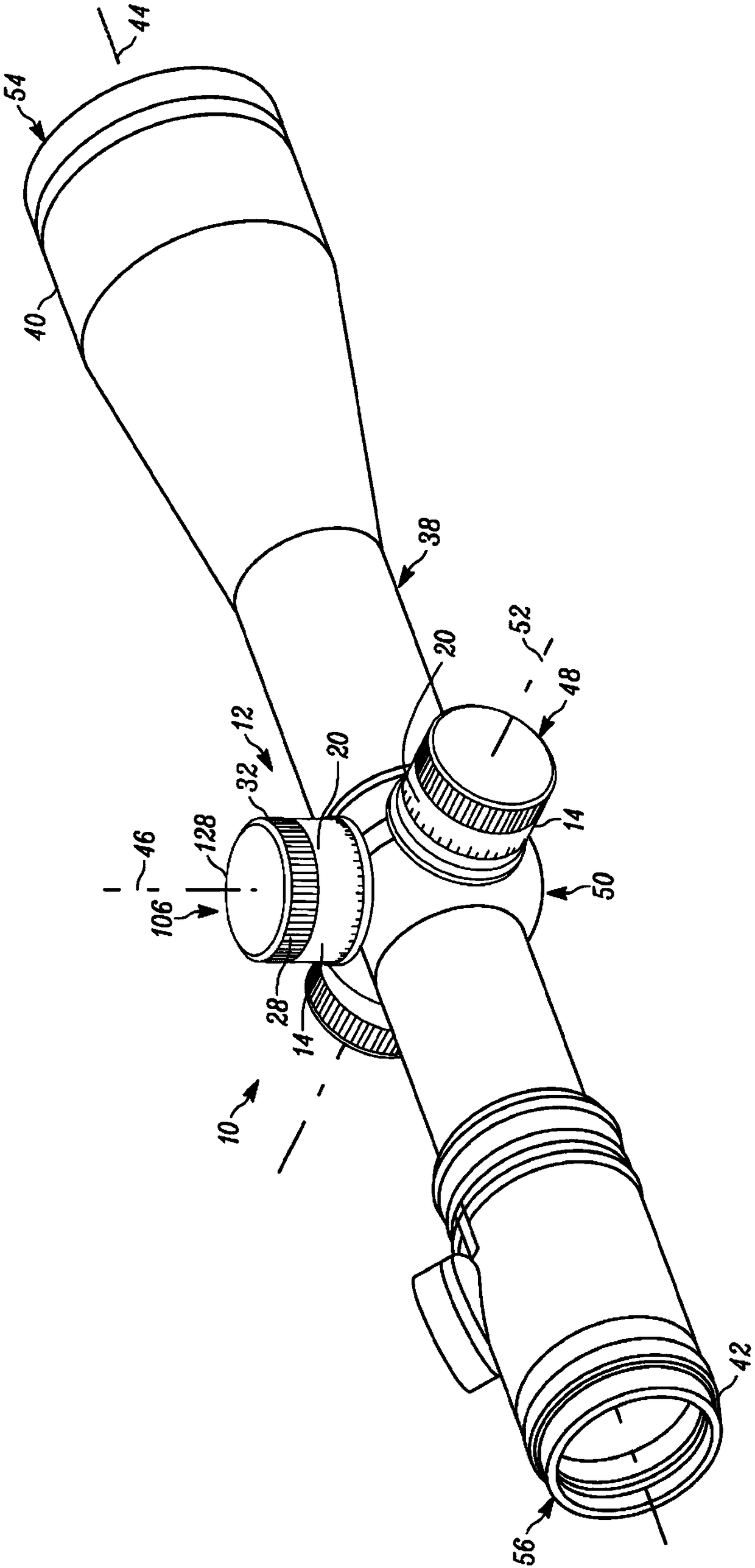
Turret with zero stop
A technology of adjusting knobs and knobs, which is applied in the direction of weapon accessories, offensive equipment, aiming devices, etc., can solve the problems of small and streamlined scopes, and achieve the effects of simple manufacturing protocol, simple use, and light weight
- Summary
- Abstract
- Description
- Claims
- Application Information
AI Technical Summary
Problems solved by technology
Method used
Image
Examples
example 1
[0167] Example 1: Zeroing a firearm
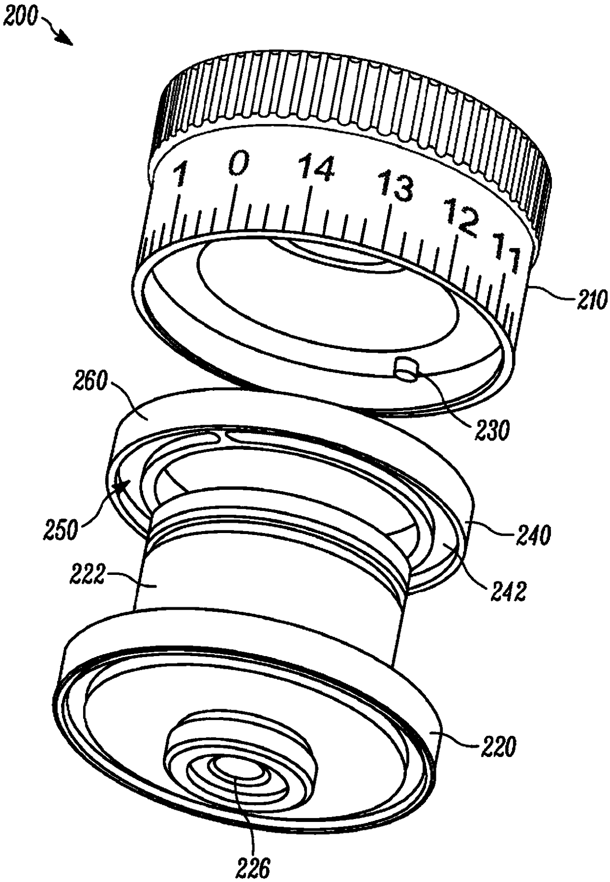
[0168] To set a zero point at a given distance (say 100 yards), the user first attaches a rifle scope to the rifle. The user will then shoot at the target. Between each shot, the user will adjust the knob until the point of impact is where they want it to be. Once the impact point is at the desired location, the user will remove the adjustment knob outer knob, then turn all zero point stop rings to their full clockwise position (could be counterclockwise if the adjustment knob pitch is in the opposite direction, which is sometimes the case in other countries is desired) until the base pin contacts the terminating end on the concentric cam track on the bottom side of the zero stop.
[0169] Next, the user will replace the adjuster knob with the "0" facing directly, after which the knob pin will align with the "start" of the cam track on the top side of the zero point stop ring. At this point, the zero stop will no longer allow clockwise ...
example 2
[0171] In the configuration of the device disclosed herein, on the first turn of the adjuster knob, the knob pin will ride inside the concentric cam track on the top side of the zero point stop ring. The zero point stop ring remains stationary on the first turn. When the first turn ends, the knob pin contacts the terminating end of the cam track so that when the second turn begins, the knob and zero stop ring rotate together. On the second turn, the base pin tracks around the concentric cam track on the bottom side of the zero point stop ring until, near the end of the second turn, it contacts the terminating end of the bottom side concentric cam track, stopping the adjustment knob all sports. Reversing will allow the adjustment knob to return to its original position or "zero stop".
example 3
[0173] In one configuration of the device disclosed herein, on the first turn, the zero point stop ring and the knob pin rotate together, with the base pin orbiting inside the bottom concentric cam track until it contacts the terminating end. At this point, a second revolution begins and the knob pin will cycle around the concentric cam track on the top side of the zero point stop ring until it hits the termination end near the end of the second rotation.
PUM
 Abstract
Description
Claims
Application Information
 - R&D Engineer
- R&D Manager
- IP Professional
- Industry Leading Data Capabilities
- Powerful AI technology
- Patent DNA Extraction
Browse by: Latest US Patents, China's latest patents, Technical Efficacy Thesaurus, Application Domain, Technology Topic, Popular Technical Reports.
© 2024 PatSnap. All rights reserved.Legal|Privacy policy|Modern Slavery Act Transparency Statement|Sitemap|About US| Contact US: help@patsnap.com


