Turritella tail cutting device

A cone screw and fixing device technology, applied in the field of kitchen utensils, can solve the problems of low work efficiency, low efficiency, affecting the business of merchants, etc., and achieve the effect of improving efficiency

Active Publication Date: 2018-11-13
徐超
View PDF5 Cites 4 Cited by
  • Summary
  • Abstract
  • Description
  • Claims
  • Application Information

AI Technical Summary

Problems solved by technology

[0002] At present, when people eat the cone snails, they need to knock off the tails of the cone snails, and then cook the cone snails before eating. In the process of tapping the tail of the snail, people often use the back of a knife or a hammer to beat one by one. This method has low work efficiency and is easy to hurt fingers.
[0003] For merchants who specialize in cooking snails for sale, they always break off the tails of the batches of snails. When customers need them, they pick an appropriate amount of snails and cook them for customers. In this way, some snail tails have been eaten It was broken, but it was not sold on the same day, and it would not have a fresh taste if it was kept for sale the next day; if the tail of the conical snail was knocked off on the spot and then cooked, the efficiency would be very low, which would affect the business of the merchant. , therefore, it has practical significance to provide a kind of taper screw tail cutting device

Method used


Image

  • Turritella tail cutting device
  • Turritella tail cutting device
  • Turritella tail cutting device

Examples


Embodiment Construction

[0022] The preferred embodiments of the present invention will be described in detail below in conjunction with the accompanying drawings: It should be understood that the preferred embodiments are only for illustrating the present invention, rather than limiting the protection scope of the present invention.

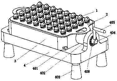
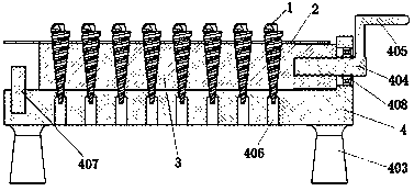
[0023] Such as Figures 1 to 5 As shown, a taper screw tail cutting device includes a taper screw fixing device 3, a supporting plate 2 and a support frame 4, the upper surface of the support frame 4 is provided with two slide rails 401, and the lower surface is provided with 4 support feet 403, the left side is provided with a limit pin fixing hole for installing a limit pin 407, the middle part is provided with regularly arranged waste holes 406, and the right side is provided with a bearing seat 402; said bearing seat 402 is provided with a bearing 408, said A screw mandrel 404 is installed in the bearing 408, and two snap rings are installed in the screw mandrel 404...


PUM


Abstract

The invention relates to a turritella tail cutting device, and belongs to the technical field of kitchen utensils. The turritella tail cutting device comprises a turritella fixing device and a supporting frame, wherein two sliding rails are arranged on the upper surface of the supporting frame; four supporting feet are arranged on the lower surface of the supporting frame; a limiting pin fixing hole is formed in the left side of the supporting frame; waste material holes which are regularly arrayed are formed in the middle part of the supporting frame; a bearing seat is arranged on the right side of the supporting frame; a bearing is arranged in the bearing seat; a screw rod is mounted in the bearing; a rotating handle is arranged at the tail end of the screw rod; sliding grooves are formed in two sides of the lower surface of the turritella tail cutting device; turritella fixing holes which are regularly arrayed are formed in the middle part of the turritella tail cutting device; anda limiting block is arranged on the right side of the turritella tail cutting device. The turritella tail cutting device disclosed by the invention is convenient, swift, safe and labor-saving, so thatthe turritella tail cutting efficiency is improved; turritella tails can be cut in batch; through rotation of the rotating handle, the turritella fixing device slides to the leftmost end to be in contact with a limiting needle, and the turritella tails can be cut off; the cut-off turritella tails can drop out from the waste material holes; and then turritella can be taken out through taking up ofthe supporting plate, so that the function of tail cutting of the turritella is realized.

Description

technical field [0001] The invention relates to a cone screw tail cutting device, which belongs to the technical field of kitchen utensils. Background technique [0002] At present, when people eat the cone snails, they need to knock off the tails of the cone snails, and then cook the cone snails before eating. In the process of taping the tails of snails, people often use the back of a knife or a hammer to beat them one by one. This method is inefficient and easily hurts fingers. [0003] For merchants who specialize in cooking snails for sale, they always break off the tails of the batches of snails. When customers need them, they pick an appropriate amount of snails and cook them for customers. In this way, some snail tails have been eaten It was broken, but it was not sold on the same day, and it would not have a fresh taste if it was kept for sale the next day; if the tail of the conical snail was knocked off on the spot and then cooked, the efficiency would be very lo...

Claims


Application Information

Patent Timeline
Patent Type & Authority Applications(China)
IPC IPC(8): A22C29/00
CPCA22C29/00
Inventor 不公告发明人
Owner 徐超
Why Eureka
Try Eureka