Omnibearing trimming device for blow molding tray

An all-round, trimming technology, applied in machine tools, grinding machines, metal processing and other directions suitable for grinding the edge of workpieces, can solve the problems of low trimming efficiency, etc., to improve trimming efficiency, smooth outer wall, and reduce labor intensity. Effect

Inactive Publication Date: 2021-01-26
王剑
View PDF0 Cites 4 Cited by
  • Summary
  • Abstract
  • Description
  • Claims
  • Application Information

AI Technical Summary

Problems solved by technology

[0005] In order to overcome the shortcomings of needing manual hand-held trimming equipment and making the trimming equipment move along the blow molding tray for trimming and low trimming efficiency, the technical problem to be solved by the invention is to provide a kind of manual trimming, Blow-molded tray all-round trimming device that can improve trimming efficiency

Method used


Image

  • Omnibearing trimming device for blow molding tray
  • Omnibearing trimming device for blow molding tray
  • Omnibearing trimming device for blow molding tray

Examples


Embodiment 1

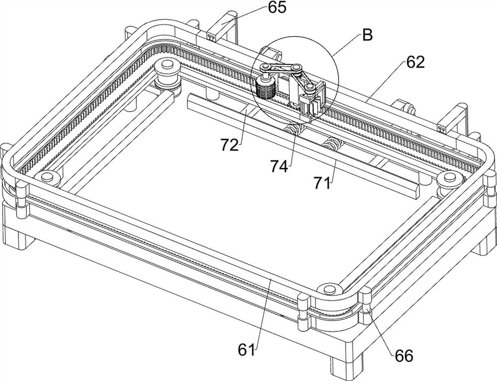
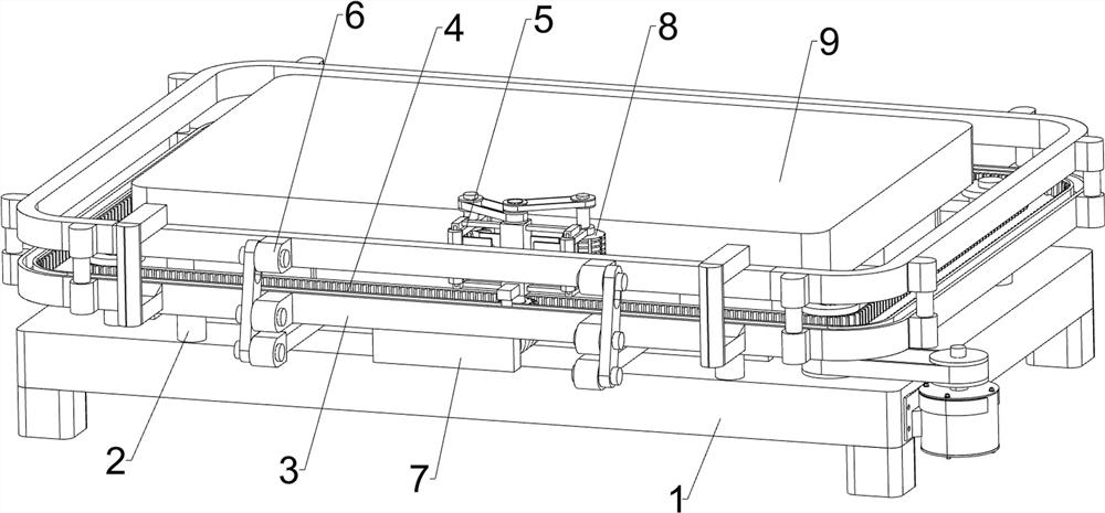
[0024] An all-round edge trimming device for a blow molding tray, such as Figure 1 to Figure 5 As shown, it includes a base 1, a support frame 2, a rail frame 3, a moving mechanism 4, a cutting mechanism 5, a movable guide frame mechanism 6, and a trigger structure 7. A plurality of support frames 2 are connected to the outside of the top of the base 1, and a plurality of support frames 2 is connected with a guide rail frame 3, a moving mechanism 4 is installed between the base 1 and the guide rail frame 3, a cutting mechanism 5 is installed on the moving mechanism 4, and a movable guide frame mechanism 6 and a triggering structure are respectively installed on the guide rail frame 3 7.

[0025] The moving mechanism 4 includes a servo motor 41, the first transmission belt set 42, a pulley 43, a rack belt 44, a fixed rack 45, a transmission gear 46, a transmission shaft 47 and a positioning frame 48, and a servo motor is installed on the front side of the right side of the bas...

Embodiment 2

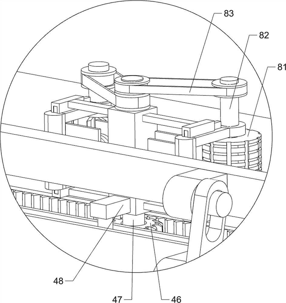
[0031] On the basis of Example 1, such as Figure 4As shown, also includes grinding mechanism 8, and grinding mechanism 8 includes grinding wheel 81, connecting shaft 82 and the 3rd transmission belt group 83, and right side sliding installation frame 52 rear parts are connected with connecting shaft 82 in rotation, on connecting shaft 82 A grinding wheel 81 is connected, and a third transmission belt set 83 is connected between the connecting shaft 82 and the transmission shaft 47 .

[0032] The transmission shaft 47 rotates through the third transmission belt set 83 to make the connecting shaft 82 rotate, and the connecting shaft 82 rotates to drive the grinding wheel 81 to rotate. The rotation of the grinding wheel 81 can polish the periphery of the blow molding tray 9, making the outer wall of the blow molding tray 9 smoother .


PUM


Abstract

The invention relates to a trimming device, in particular to an omnibearing trimming device for a blow molding tray. According to the omnibearing trimming device for the blow molding tray, manual trimming is not needed, and the trimming efficiency can be improved. The omnibearing trimming device for the blow molding tray comprises a base, a guide rail frame, a moving method, a cutting mechanism, aguide frame mechanism and a triggering structure, wherein a plurality of supporting frames are connected to the upper outer side of the base; the guide rail frame is connected between the support frames; the moving mechanism is mounted between the base and the guide rail frame; the cutting mechanism is mounted on the moving mechanism; the guide rail frame is provided with the movable guide framemechanism; and the triggering structure is mounted on the guide rail frame. The movable guide frame mechanism can be triggered to work through the trigger structure, the movable guide frame mechanismcan work to enable the cutting mechanism to be tightly attached to the blow molding tray, the blow molding tray can be trimmed through cooperation of the moving mechanism and the cutting mechanism, manual trimming is not needed, the trimming efficiency can be improved, and labor intensity can be reduced.

Description

technical field [0001] The invention relates to an edge trimming device, in particular to an all-round edge trimming device for a blow molding tray. Background technique [0002] Blow-molded tray is a product formed by a rapidly developing plastic processing method. When a blow-molded tray with a large area is cut into a blow-molded tray with a suitable area, there will be more waste left around the blow-molded tray. In this way, it is necessary to trim the cut blow-molded tray. At present, the trimming of the cut blow-molded tray is generally carried out manually. The pallet moves, so the labor intensity of the worker is high, and the arm is prone to soreness after a long time of work, resulting in a decrease in trimming efficiency, and the worker needs to be close to the blow molding pallet during trimming, so that the waste material is easy to splash and hurt the worker. [0003] Therefore, it is necessary to develop a blow molding tray omnidirectional trimming device th...

Claims


Application Information

Patent Timeline
Patent Type & Authority Applications(China)
IPC IPC(8): B26D1/36B26D7/00B26D7/27B24B9/20
CPCB24B9/20B26D1/36B26D7/0006B26D7/27
Inventor 王坚
Owner 王剑
Why Eureka
Try Eureka