
Trimming device based on cam structure

A cam and trimming technology, applied in metal processing and other directions, can solve the problems of inconsistent trimming thickness, reduced cutter efficiency, and large space occupied, so as to ensure the quality of cutting glue, improve trimming efficiency, and take up less space. Effect

Active Publication Date: 2016-04-20
SUZHOU HYH AUTOMATION EQUIP CO LTD
View PDF5 Cites 3 Cited by
  • Summary
  • Abstract
  • Description
  • Claims
  • Application Information

AI Technical Summary

Problems solved by technology

The traditional glue cutting method is to use manual glue cutting. Manual glue cutting is not only inefficient, but also has high labor input costs, and because of the difference in worker skills, it will inevitably lead to inconsistent thickness of the cut edge, which cannot guarantee the consistency of product quality.
[0003] In order to solve the above problems, automatic edge trimming devices have appeared. Some edge trimming devices fix the product and cut the glue through an automatic cutter. Moving the cutter up and down relatively reduces the efficiency, and the entire device has a complicated structure and takes up more space. Big

Method used


Image

  • Trimming device based on cam structure
  • Trimming device based on cam structure
  • Trimming device based on cam structure

Examples


Embodiment

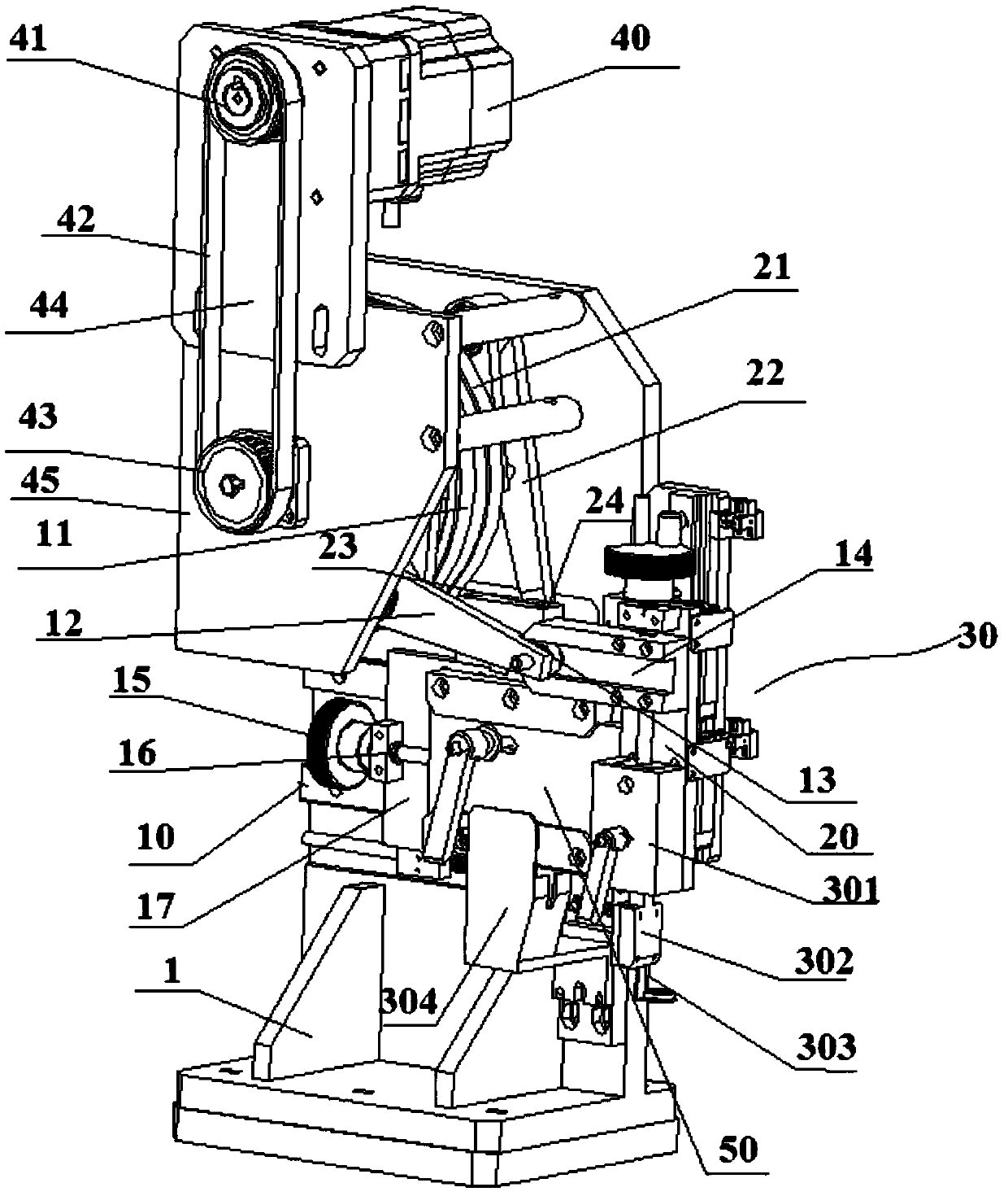
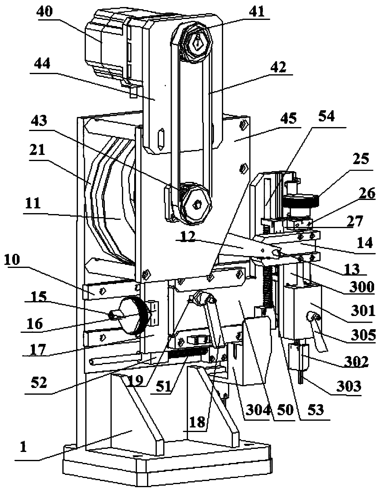
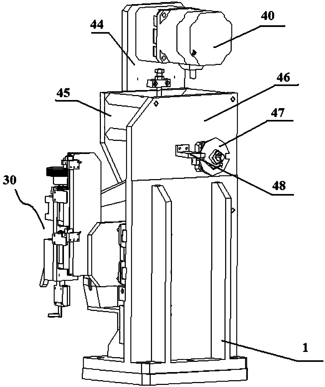
[0027] like Figure 1-3 As shown, this embodiment discloses a trimming device based on a cam structure, which mainly includes: a base assembly 1, an X-axis slide rail 10 and a Z-axis slide rail 20 arranged on the base assembly 1, and a The cutter assembly 30 moves in the X-axis direction along the X-axis slide rail 10 , and the cutter assembly 30 can move in the Z-axis direction along the Z-axis slide rail 20 . In this embodiment, the above-mentioned X-axis direction is a horizontal direction, and the above-mentioned Z-axis direction is a vertical direction.

[0028] The drive unit of above-mentioned trimming device is motor 40, and above-mentioned motor 40 has speed reducer, and the output shaft of above-mentioned speed reducer is sleeved on the driving wheel 41, and above-mentioned driving wheel 41 drives a synchronous wheel 43 to rotate by synchronous belt 42, and above-mentioned synchronous The wheel 43 is connected to the above-mentioned rotating shaft, and the X-axis ca...


PUM


Abstract

The invention discloses a trimming device based on a cam structure. The trimming device comprises a motor, the motor drives a rotary shaft to rotate, an X-axis cam and a Z-axis cam are arranged on the rotary shaft, the X-axis cam is connected with an X-axis connecting rod, and the end of the X-axis connecting rod is connected with a first cam driven bearing. The first cam driven bearing moves in an X-axis sliding groove, and a groove plate with the X-axis sliding groove is fixed to a cutter assembly. The Z-axis cam is connected with a Z-axis connecting rod, a second cam driven bearing is arranged at the end of the Z-axis connecting rod, the second cam driven bearing slides in a Z-axis sliding groove, and a groove plate with the Z-axis sliding groove is fixed to the cutter assembly. When the motor drives the rotary shaft to drive the X-axis cam and the Z-axis cam to rotate at the same time, the cutter assembly is moved in place in the X-axis direction and the Z-axis direction through the cooperation of the X-axis cam and the Z-axis cam, and then trimming is carried out through a cutter. The trimming device is simple in structure, reasonable in design, high in trimming efficiency and small in occupied space.

Description

technical field [0001] The invention relates to the field of automatic cutting devices, in particular to an automatic glue cutting device, in particular to an edge trimming device based on a cam structure. Background technique [0002] Some small auto parts are wrapped with a layer of glue on the outside of the product. In the process of wrapping the glue, the thickness of the glue is often inconsistent. Therefore, it is necessary to cut the wrapped glue material to make the outer wrapping of the product consistent and ensure the quality of the product. The traditional glue cutting method is to use manual glue cutting, which is not only inefficient, but also has high labor input costs, and because of the difference in worker skills, it will inevitably lead to inconsistent thickness of the cut edge, which cannot guarantee the consistency of product quality. [0003] In order to solve the above problems, an automatic edge trimming device has appeared. Some edge trimming devic...

Claims


Application Information

Patent Timeline
Patent Type & Authority Applications(China)
IPC IPC(8): B26D1/02B26D5/06B26D7/26B26D7/22
CPCB26D1/02B26D5/06B26D7/22B26D7/2614B26D7/2628
Inventor 薛华
Owner SUZHOU HYH AUTOMATION EQUIP CO LTD
Learn More