
Touch panel with antenna and touch display device

A touch display device and touch panel technology, applied in the input/output process of data processing, instruments, electrical digital data processing, etc., can solve problems affecting internal circuit layout, signal interference, and the thickness of electronic devices cannot be further reduced.

Pending Publication Date: 2017-03-29
J TOUCH CORPORATION
View PDF5 Cites 17 Cited by
  • Summary
  • Abstract
  • Description
  • Claims
  • Application Information

AI Technical Summary

Problems solved by technology

However, electronic devices are gradually developing towards thinner and higher density. Traditional antenna elements and their installation methods will occupy the space inside the electronic device and affect the internal circuit layout, so that the thickness of the electronic device cannot be further reduced, and it will increase the number of electronic devices. The assembly steps and material cost of
In addition, the traditional antenna elements and their setting methods are likely to cause signal interference, affecting the performance of the antenna and touch panel

Method used


Image

  • Touch panel with antenna and touch display device
  • Touch panel with antenna and touch display device
  • Touch panel with antenna and touch display device

Examples


Embodiment Construction

[0044] Some typical embodiments embodying the features and advantages of the present application will be described in detail in the description in the following paragraphs. It should be understood that the present application can have various changes in different aspects without departing from the scope of the present application, and the description and drawings therein are regarded as illustrative in nature rather than limiting the present application.

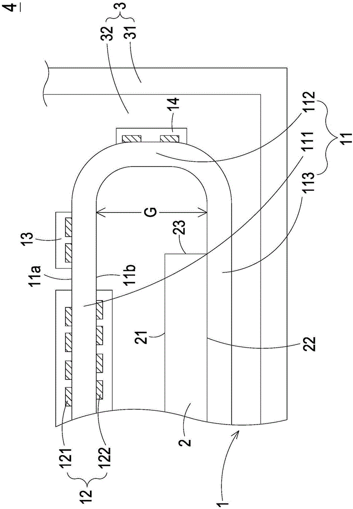
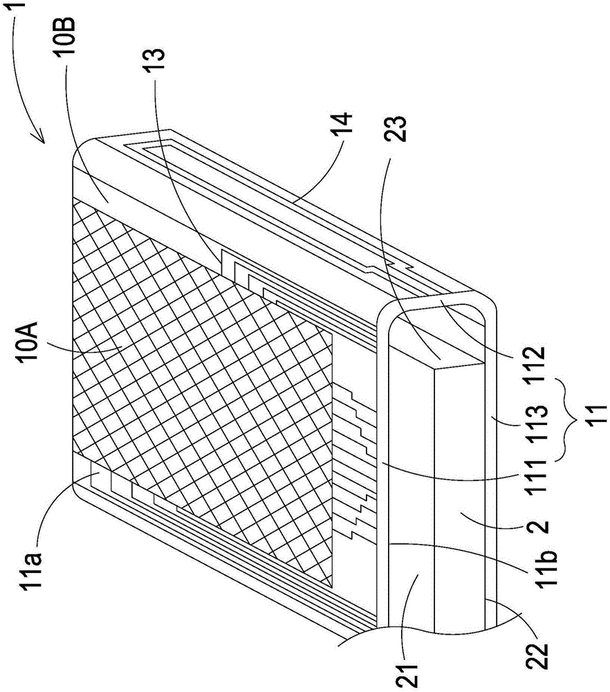
[0045] see figure 1 and 2 ,in figure 1 It is a schematic cross-sectional structure diagram of the touch display device according to the first preferred embodiment of the present application, and figure 2 for figure 1 A schematic diagram of the partial structure of the combination of the touch panel with antenna and the display module. The touch display device 4 of this case can be applied to electronic devices with wireless communication functions, such as but not limited to mobile phones, tablet computers, portable com...


PUM

PropertyMeasurementUnit
Line widthaaaaaaaaaa

Abstract

The invention relates to a touch panel with an antenna and a touch display device. The touch display device comprises the touch panel and a display module; the touch panel comprises a flexible transparent film with a first section and a bending part; a metal mesh line, which is arranged on at least one surface of the flexible transparent film and arranged in the first section, and is structured as a visible touch area; a plurality of metal wires, which are arranged on at least one surface of the flexible transparent film and arranged at the periphery of the visible touch area, and electrically connected with the metal mesh line; and an antenna radiator, which is arranged on at least one surface of the flexible transparent film, and located at the bending part, wherein the antenna radiator, the metal mesh line and at least one of the plurality of metal wires are located at the same surface and molded on the surface once. The display module includes a side, and the antenna radiator is opposite to the side of the display module. The antenna radiator is formed by using a same process step of forming an induction electrode of the visible touch area and metal wires in a peripheral line area, so that the overall thickness is consistent.

Description

technical field [0001] This case relates to the field of touch display, in particular to a touch panel with an antenna and a touch display device. Background technique [0002] At present, touch technology has been widely used in display devices of various electronic devices, so that users can control the actions of the electronic devices by touch. Generally speaking, a touch display device of an electronic device includes a touch panel and a display module. The touch panel includes a substrate, a plurality of sensing electrodes and a plurality of metal leads, wherein the substrate can be divided into a visible touch area and a peripheral circuit area, a plurality of sensing electrodes are arranged on the substrate and arranged in the visible touch area, and a plurality of The metal leads are arranged on the substrate and arranged in the peripheral circuit area, and each metal lead is electrically connected to the corresponding sensing electrode. The touch panel is bonded ...

Claims


Application Information

Patent Timeline
IPC IPC(8): G06F3/041
Inventor 叶裕洲颜毓宏林庭庆崔久震庄家硕
Owner J TOUCH CORPORATION
Learn More