Steel bar straightening and cutting equipment for construction site

A technology for construction sites and cutting equipment, applied in the field of machinery, can solve problems such as reduced work efficiency, roughness, and insufficient straightening

Inactive Publication Date: 2018-11-13
HEBEI JIASHICHENG ENERGY TECH CO LTD
View PDF6 Cites 7 Cited by
  • Summary
  • Abstract
  • Description
  • Claims
  • Application Information

AI Technical Summary

Problems solved by technology

[0002] At present, with the rapid development of the economy, the development of industry and cities, it is required to build a large number of houses. As an indispensable material in construction, steel bars need to be straightened and cut before use. At present, the steel bars on the market The straightening and cutting equipment is too rough, the straightening effect is not ideal, and the phenomenon of steel bar movement often occurs, resulting in insufficient straightening, requiring multiple readjustments, and the straightening machine can only be straightened, and fixed-length steel bars need to be used Cutting operations are also required, which reduces work efficiency
[0003] The Chinese document is CN107617703A, a kind of straightening and cutting equipment for building steel bars, which can automatically straighten and cut building steel bars. The process does not require manual intervention, the structure is simple, and the cutting is accurate; and the steel bar section is convenient to discharge after cutting, but there is a machine failure. The steel bars fly out Problems that hurt staff

Method used


Image

  • Steel bar straightening and cutting equipment for construction site
  • Steel bar straightening and cutting equipment for construction site
  • Steel bar straightening and cutting equipment for construction site

Examples


Embodiment Construction

[0029] The technical solutions in the embodiments of the present invention will be clearly and completely described below in conjunction with the accompanying drawings in the embodiments of the present invention. Obviously, the described embodiments are only some of the embodiments of the present invention, not all of them. Based on the embodiments of the present invention, all other embodiments obtained by persons of ordinary skill in the art without making creative efforts belong to the protection scope of the present invention.

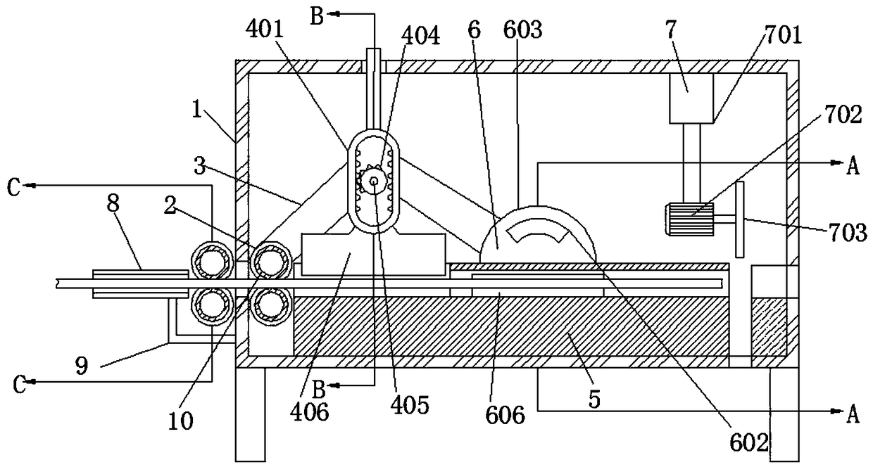
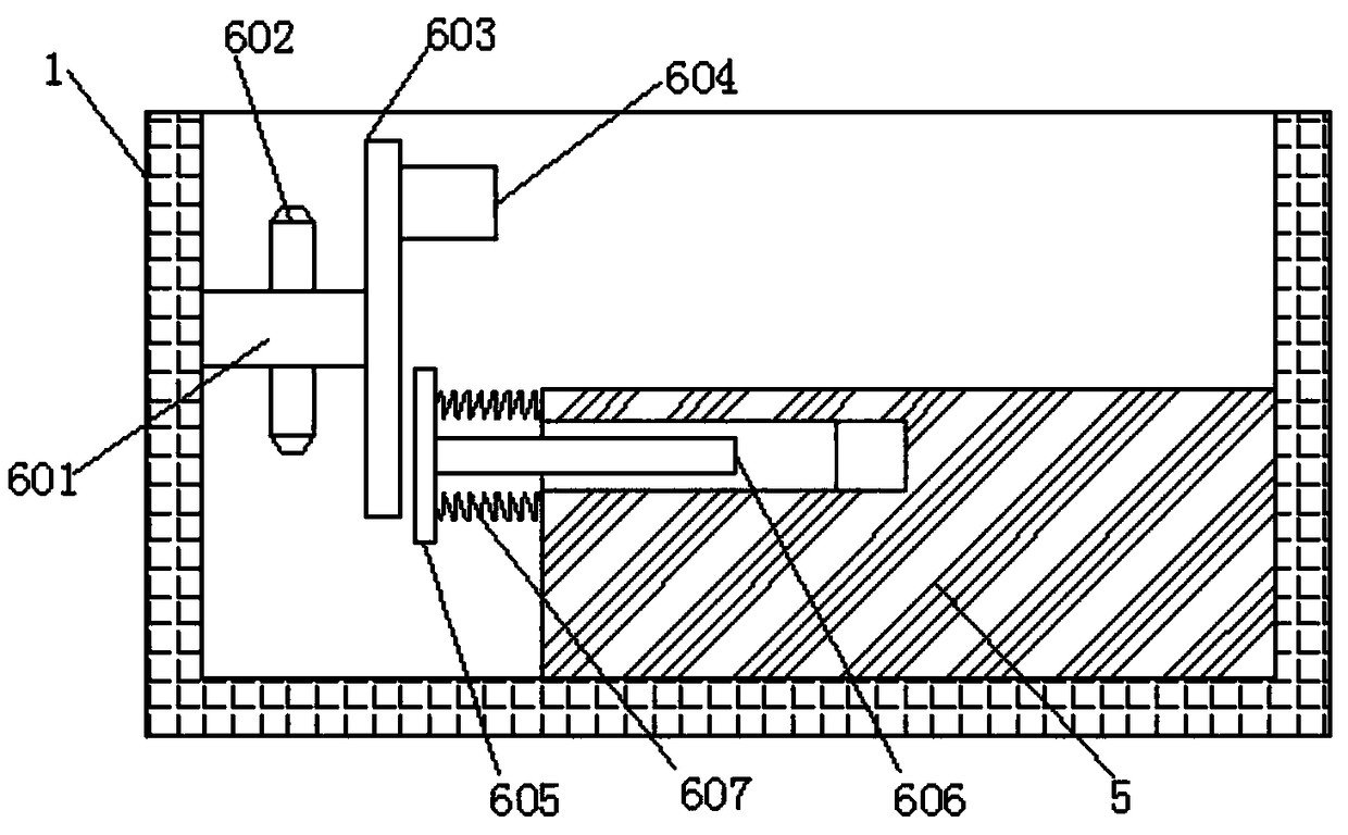
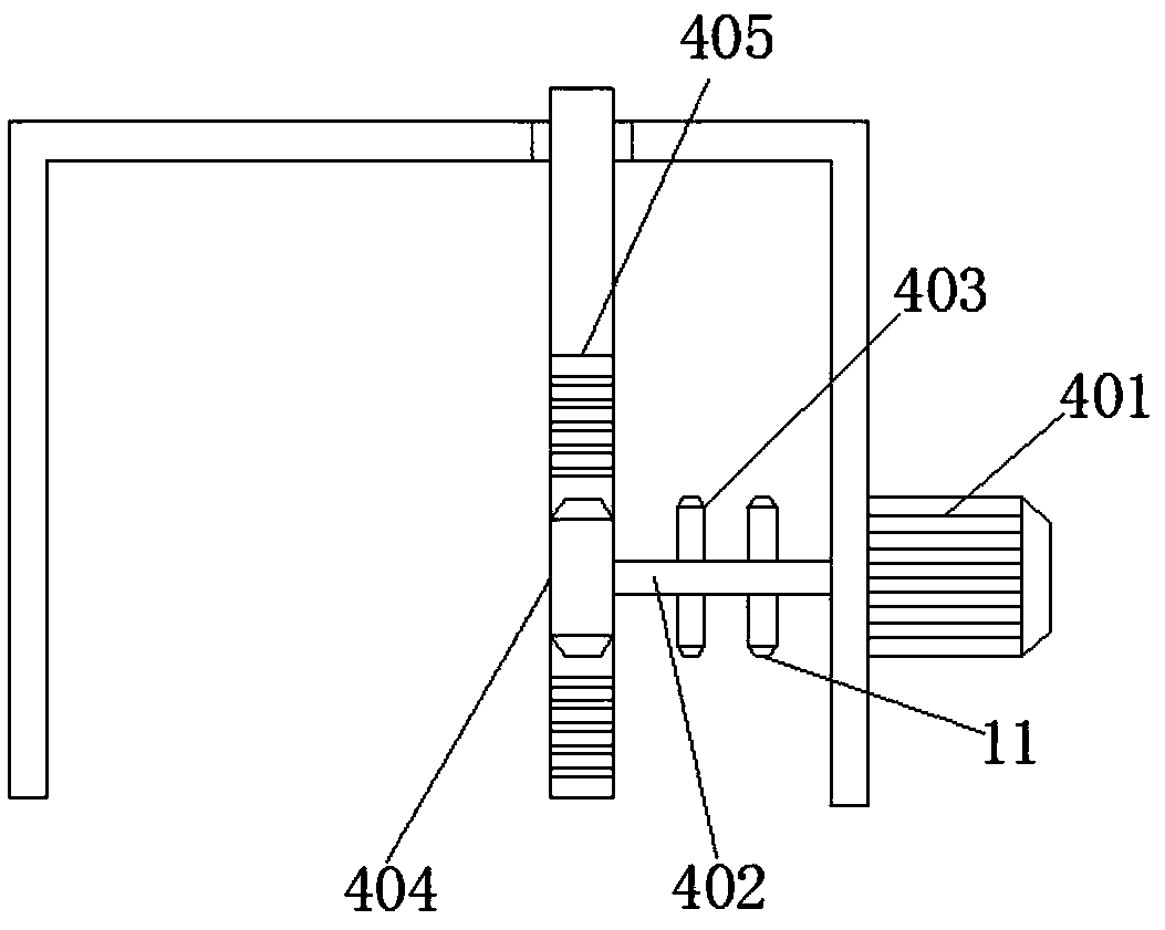
[0030] see Figure 1-3 , the present invention provides a technical solution:

[0031] A construction site steel bar straightening and cutting equipment, comprising a fixed box 1, a first roller 2 and a second roller, the lower end of the fixed box 1 is fixedly connected with a bracket, and the outer wall of the fixed box 1 is fixedly connected with a fixed frame 9, fixed The frame 9 is fixedly connected with a guide tube 8. The guide tube 8 guide...


PUM


Abstract

The invention discloses steel bar straightening and cutting equipment for a construction site. The equipment comprises a fixed box, a first roller and a second roller, the lower end of the fixed box is fixedly connected with a support, the two ends of the first roller and the two ends of the second roller are rotationally connected to the inner side wall of the fixed box correspondingly, and a first gear is fixedly connected to the outer side wall of the first roller in a sleeving mode. After a steel bar is straightened through a third roller and a fourth roller, the steel bar is straightenedagain through the first roller and the second roller, so that a good straightening effect is achieved, meanwhile, the steel bar can be driven to move, and manual delivery is not needed; an annular rack moves up and down, then a pressing block is driven to strike the steel bar up and down in a reciprocating mode, and longitudinal steel bar straightening is carried out; an extrusion block is used for repeatedly extruding a connecting block, so that a connecting plate transversely strikes the steel bar, and transverse steel bar straightening is carried out; and a cutting mechanism is added so that cutting can be carried out by controlling the movement of a cutting motor up and down through an electric telescopic rod.

Description

technical field [0001] The invention relates to the technical field of machinery, in particular to a steel bar straightening and cutting device for a construction site. Background technique [0002] At present, with the rapid development of the economy, the development of industry and cities, it is required to build a large number of houses. As an indispensable material in construction, steel bars need to be straightened and cut before use. At present, the steel bars on the market The straightening and cutting equipment is too rough, the straightening effect is not ideal, and the phenomenon of steel bar movement often occurs, resulting in insufficient straightening, requiring multiple readjustments, and the straightening machine can only be straightened, and fixed-length steel bars need to be used Also need to carry out cutting operation when, have reduced working efficiency. [0003] The Chinese document is CN107617703A, a kind of straightening and cutting equipment for bu...

Claims


Application Information

Patent Timeline
Patent Type & Authority Applications(China)
IPC IPC(8): B21F1/02B21F11/00
CPCB21F1/026
Inventor 白莉莉
Owner HEBEI JIASHICHENG ENERGY TECH CO LTD
Why Eureka
Try Eureka