
Brake light control for vehicle braking systems

A vehicle brake and brake light technology, which is applied in the direction of brake transmission, brakes, vehicle components, etc., can solve the problems that sensors cannot be applied, increase the number of rear cars colliding with front cars, and cannot be used to control brake lights, etc., to achieve Safe follow-up braking upgrade guarantee and the effect of improving driving safety

Active Publication Date: 2022-04-01
ROBERT BOSCH GMBH
View PDF19 Cites 0 Cited by
  • Summary
  • Abstract
  • Description
  • Claims
  • Application Information

AI Technical Summary

Problems solved by technology

However, prior art vehicles cannot reflect this difference in braking conditions, thus potentially increasing the chances of rear-end collisions with vehicles in front
[0004] In addition, although a sensor is installed at the brake pedal in the vehicle of the prior art, so that the detection signal of the sensor can control whether the brake light is illuminated or not, but with the development of the application of automatic driving technology in automobiles, This kind of sensor cannot be applied in the process of automatic driving of the car
That is, in a car that is driving itself, usually the driver does not need to press the brake pedal at all, at which point the sensor cannot be used to control the brake lights

Method used


Image

  • Brake light control for vehicle braking systems
  • Brake light control for vehicle braking systems

Examples


Embodiment Construction

[0025] In the various figures of the present invention, structurally identical or functionally similar features are indicated by the same reference numerals.

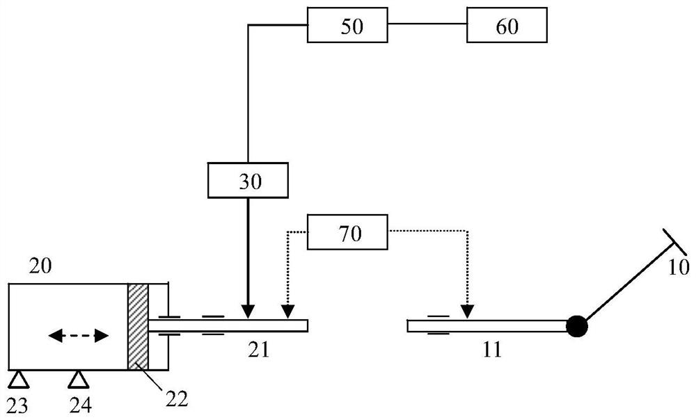
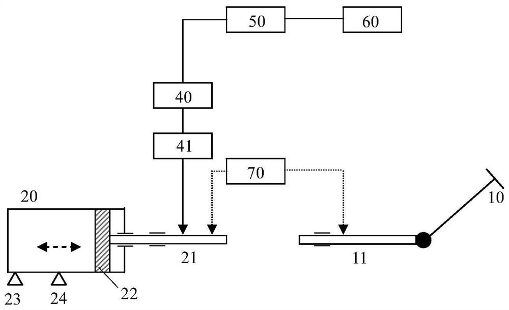
[0026] figure 1 A vehicle braking system 100 according to one embodiment of the invention is schematically shown. The vehicle braking system 100 includes a brake pedal 10 and a brake master cylinder (or called brake master pump) 20 . Master cylinder 20 includes a piston 22 movable back and forth within its cylinder. There are also two hydraulic ports 23 and 24 in the brake master cylinder 20, which can be respectively connected with brake cylinders (or called brake cylinders) for directly providing hydraulic braking force to the wheels. Master brake cylinder 20 has an input shaft 21 . The input shaft 21 is connected with the piston 22 for driving the piston 22 to move linearly in the cylinder of the hydraulic master cylinder 20 to pressurize the hydraulic oil in the cylinder and output it to the hydraulic ports 23 an...


PUM


Abstract

The invention discloses a vehicle brake system, which comprises: a hydraulic master cylinder, which has a cylinder body and a piston movably arranged in the cylinder body; and a brake pedal, which can be linked with a first moving part a brake driver, used to drive the piston to move in the cylinder via a second moving part, so as to pressurize and output the hydraulic oil from the cylinder, and a brake light located on the outside of the vehicle, wherein, in the first A differential stroke sensor is arranged between a moving part and the second moving part, for detecting the motion difference between the first moving part and the second moving part, and the luminous intensity of the brake light is proportional to the absolute value of the differential amount of motion detected by the differential stroke sensor. The invention also discloses a vehicle adopting the vehicle braking system.

Description

technical field [0001] The invention basically relates to the brake light control of a vehicle braking system, in particular of a vehicle electric drive braking system. Background technique [0002] A braking system of a vehicle such as an automobile mainly includes a master cylinder and a brake pedal. The brake pedal is linked with the piston in the brake master cylinder, so that the piston can drive the hydraulic oil in the brake master cylinder to provide braking force to the wheels. While the wheels are being braked, the brake lights at the rear of the vehicle are illuminated accordingly, thereby providing a warning to other vehicles that may be behind the vehicle. [0003] During the actual running of the vehicle, the driver may press the brake pedal with different strengths and hope to brake the wheels with different strengths for different road conditions. However, the varying degrees of braking of the vehicle in front cannot be reflected in the glow of the rear bra...

Claims


Application Information

Patent Timeline
Patent Type & Authority Patents(China)
IPC IPC(8): B60T13/74B60Q1/44
CPCB60T13/745B60Q1/444
Inventor 陈俊利王志忠
Owner ROBERT BOSCH GMBH
Learn More