Conveying roller shaft

A technology of conveying rollers and conveying roller tables, which is applied in the direction of conveyor objects, rollers, transportation and packaging, etc., which can solve the problems of inconvenient installation, complicated processing, and high noise, and achieve convenient processing, reduce pollution, and reduce noise Effect

Pending Publication Date: 2018-11-13
ZHEJIANG DAMON IND EQUIP CO LTD
View PDF10 Cites 0 Cited by
  • Summary
  • Abstract
  • Description
  • Claims
  • Application Information

AI Technical Summary

Problems solved by technology

The metal connecting body has some disadvantages: it collides with the frame and the shaft core, and the noise is large; at least it includes the internal thread, the end, the connection part connected with the shaft core, and the plane on the end for the knob, so the processing process is complicated ; It is sandwiched between the shaft core and the frame, and the installation process is inconvenient

Method used


Image

  • Conveying roller shaft
  • Conveying roller shaft
  • Conveying roller shaft

Examples


Embodiment Construction

[0023] The invention will be further described below in conjunction with the embodiments in the accompanying drawings.

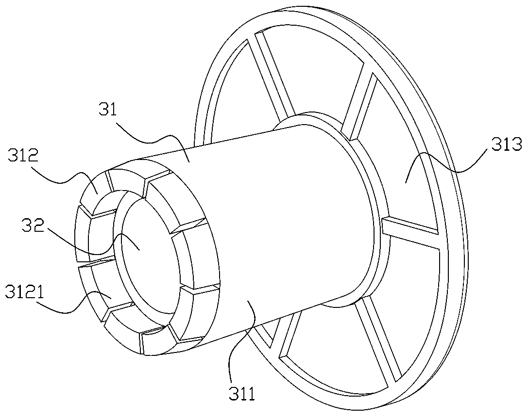
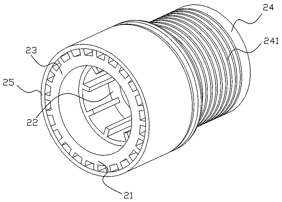
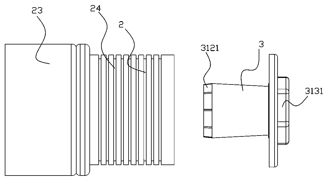
[0024] Such as Figure 1 to Figure 4 The conveying roller shaft shown includes a drum 1 and an inner sleeve 2 located on the side of the drum 1, the end of the inner sleeve 2 is provided with a connecting piece 3, and one end of the connecting piece 3 is fixed on the frame of the conveying roller table. It is characterized in that: the inner shaft sleeve 2 includes a sleeve body 21 and a retaining ring 22 inside the sleeve body 21 , the connector 3 includes a connecting body 31 and a threaded body 32 inside the connecting body 31 , and the threaded body 32 is provided with internal threads. The retaining ring 22 can be an annular structure that is integrally injection molded and connected or interference-connected in the sleeve body 21 , or can be a bearing inner ring structure of a bearing disposed in the sleeve body 21 . The threaded body 32 has a first m...


PUM


Abstract

The invention provides a conveying roller shaft. The conveying roller shaft comprises a roller and an inner shaft sleeve positioned on the side part of the roller, wherein the end part of the inner shaft sleeve is equipped with a connector; and one end of the connector is fixedly arranged on a rack of a conveying roller path. The conveying roller shaft is characterized in that the end cover comprises a cover body and a blocking ring arranged in the cover body; the connector comprises a connecting body and a threaded body positioned at the inner side of the connecting part; inner threads are arranged on the threaded body; and rigidity of one material of the threaded body is greater than that of the material of the connector. The conveying roller shaft is small in structure noise, is low incost, and is convenient to process and mount.

Description

technical field [0001] The invention relates to the technical field of logistics conveying equipment, in particular to a conveying roller. Background technique [0002] In the field of logistics transmission or the collection and winding work of mechanical equipment, the roller shaft that rotates around its own axis is an indispensable part. The roller shaft structure in the prior art often includes a shaft core and a shaft sleeve outside the shaft core. The roller body of the first layer is provided with a bearing between the shaft core and the roller body, and the roller body is connected to the driving device through a connecting component to obtain the power required for rotation. [0003] The shaft core is fixed on the frame of the equipment, and the structure for fixing the shaft core is mostly a metal connecting body with internal threads. One end of the metal connecting body is fixed on the frame, and the other end is connected to the shaft core. The metal connectin...

Claims


Application Information

Patent Timeline
Patent Type & Authority Applications(China)
IPC IPC(8): B65G39/02B65G39/09
CPCB65G39/02B65G39/09
Inventor 邵利强
Owner ZHEJIANG DAMON IND EQUIP CO LTD
Why Eureka
Try Eureka