
Lift signal transmission device

A signal transmission and elevator technology, applied in transportation, packaging, elevators, etc., can solve problems such as increased cost of elevator equipment manufacturers, signal line wiring, etc., and achieve the effect of preventing disconnection and suppressing cost increases

Active Publication Date: 2018-11-13
MITSUBISHI ELECTRIC BUILDING TECH SERVICE CO LTD
View PDF6 Cites 0 Cited by
  • Summary
  • Abstract
  • Description
  • Claims
  • Application Information

AI Technical Summary

Problems solved by technology

At this time, the signal line needs to be routed outside the hoistway inside the building. However, many other signal lines are often arranged outside the hoistway, so it is difficult for elevator equipment manufacturers to route the additional signal lines outside the hoistway.
Therefore, it is necessary to entrust the electrical construction company with the wiring of the signal line, which causes an increase in the cost of the elevator equipment manufacturer.
In addition, when many signal lines are arranged, the possibility of disconnection due to deterioration of the signal lines increases
In addition, when installing a switch on the elevator monitoring panel or changing the specification of the monitoring panel, it may be necessary to transmit a new type of signal between the monitoring panel and the elevator control panel. may produce the same problem as above

Method used


Image

  • Lift signal transmission device
  • Lift signal transmission device

Examples


Embodiment Construction

[0011] Embodiments of the present invention will be described below using the drawings. Hereinafter, the same reference numerals will be assigned to the same elements in all the drawings and will be described. In addition, in the description herein, the reference numerals described above are used as necessary.

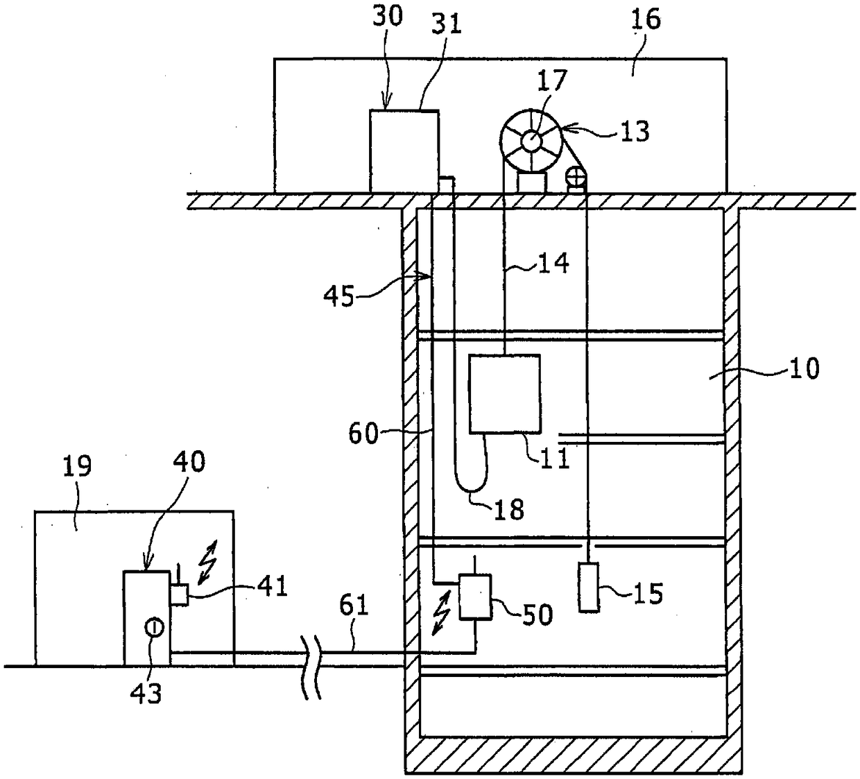
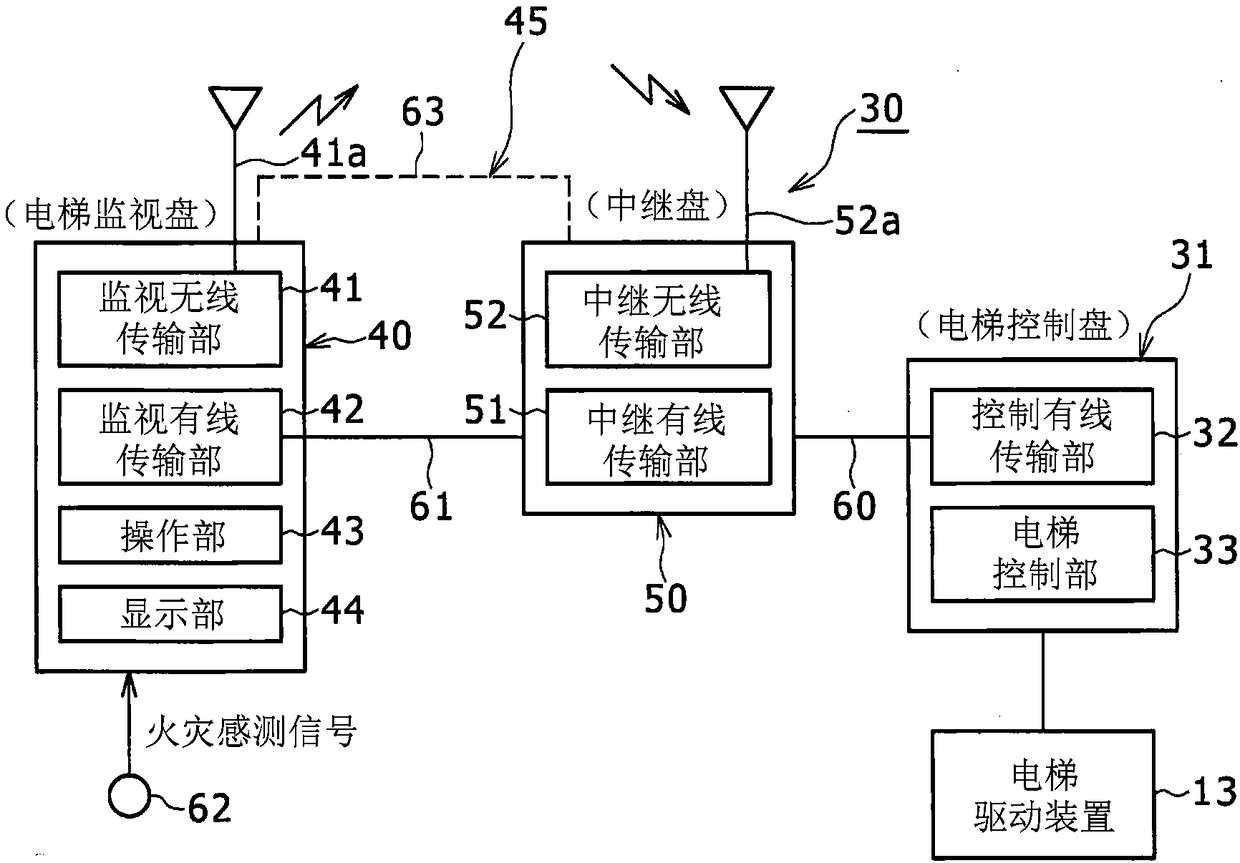
[0012] figure 1 It is a diagram showing an elevator including the elevator signal transmission device 30 of the embodiment. figure 2 It is a block diagram of the elevator signal transmission device 30 .

[0013] An elevator is configured to include a car 11 arranged in a hoistway 10 of a building, an elevator driving device 13 and an elevator signal transmission device 30 . The car 11 is connected to a counterweight 15 via ropes 14 . The elevator driving device 13 is arranged in a machine room 16 and has a traction machine 17 . The machine room 16 is arranged, for example, on the roof or the uppermost floor of a building. The rope 14 is wound around a traction m...


PUM


Abstract

The invention provides a lift signal transmission device. The lift signal transmission device (30) comprises a signal path (45) transmitting signals between a lift control board (31) and a lift monitoring board (40). The lift control board (31) is mounted in a building to control a lift car (11) ascending and descending in a shaft (10) to ascend and descend. The lift monitoring board (40) is arranged in a floor lower than the floor provided with the lift control board (31) in the building or in a space different from the space provided with the lift control board (31) and comprises a display part displaying the operating condition of the lift and an operation part (43) indicating the operation of the lift and monitors the operation of the lift. At least one part of the signal path outsidethe shaft (10) in the signal path (45) is wireless.

Description

technical field [0001] The invention relates to an elevator signal transmission device. Background technique [0002] Generally, for the purpose of coping with aging, improving functions, etc., remodeling work called modernization is performed on an elevator as needed. In this conversion work, a function of transmitting a new type of signal for improving elevator functions and the like may be added between the elevator monitoring panel that monitors the operation of the elevator and the elevator control panel that controls the elevator. For example, there is a case where a function is added to make the elevator control panel transmit an instruction to control operation in case of fire when the elevator monitoring panel receives a fire detection signal from the fire alarm. [0003] Japanese Patent Application Laid-Open No. 2006-321576 describes a structure in which signals are wirelessly transmitted between the car and an elevator control device that drives a traction machin...

Claims


Application Information

Patent Timeline
IPC IPC(8): B66B1/06B66B1/34B66B1/46B66B3/00B66B5/00
CPCB66B1/06B66B1/3423B66B1/46B66B3/002B66B5/0018
Inventor 井上雅司
Owner MITSUBISHI ELECTRIC BUILDING TECH SERVICE CO LTD
Features
  • Generate Ideas
  • Intellectual Property
  • Life Sciences
  • Materials
  • Tech Scout
  • Unparalleled Data Quality
  • Higher Quality Content
  • 60% Fewer Hallucinations
Learn More