
Power supply system

A power supply system and power supply technology, applied in the field of power supply systems, can solve problems such as voltage reduction of smoothing capacitors, and achieve the effect of reducing the number of parts and suppressing cost increase

Active Publication Date: 2019-08-23
HONDA MOTOR CO LTD
View PDF7 Cites 0 Cited by
  • Summary
  • Abstract
  • Description
  • Claims
  • Application Information

AI Technical Summary

Problems solved by technology

In such a fault detection device, if the contactor is turned off while the smoothing capacitor included in the load is being charged by the power supply, the electric charge charged in the smoothing capacitor is charged into the accumulator for auxiliary machinery, so that the smoothing capacitor The voltage is gradually reduced

Method used


Image

  • Power supply system
  • Power supply system
  • Power supply system

Examples


no. 1 approach >

[0083] In the following, on the one hand, refer to the attached Figure 1 Aspects of the first embodiment of the present invention will be described.

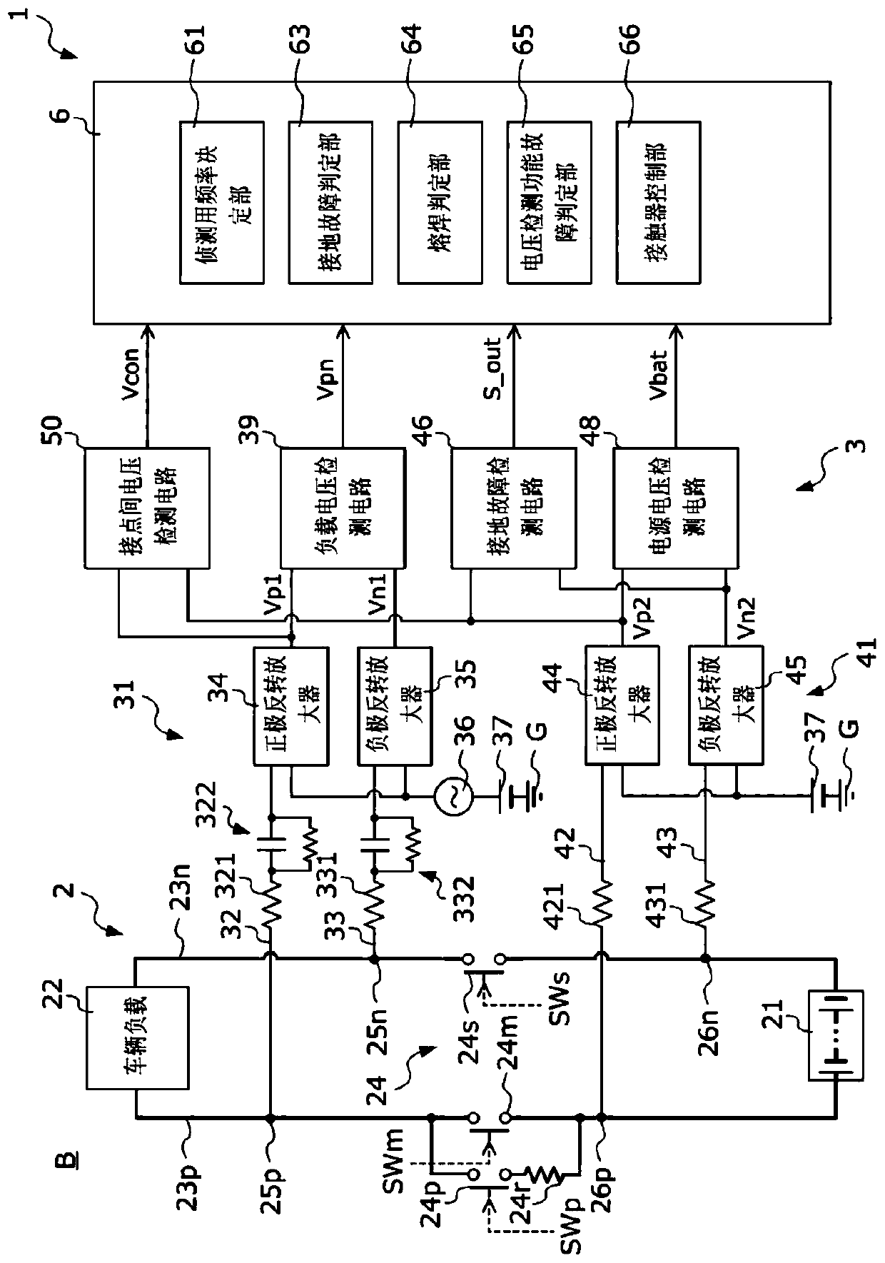
[0084] figure 1 It is a figure which shows the structure of the power supply system 1 of this embodiment. The power supply system 1 is mounted on a vehicle body B of an electric vehicle such as a battery-driven vehicle, a hybrid vehicle, or a fuel cell vehicle.

[0085] The power supply system 1 includes a non-ground circuit 2, a state detection circuit 3 connected to the non-ground circuit 2 and generating various signals corresponding to the state of the non-ground circuit 2, and a device for controlling the non-ground circuit 2 and the state detection circuit 3. Electronic control unit 6 (hereinafter, the abbreviation of "ECU6" is used).

[0086] The non-grounded circuit 2 includes a power supply 21 generating high-voltage direct current, a vehicle load 22, a positive high-voltage power line 23p connecting the positive po...

no. 2 approach >

[0159] Next, on the one hand, referring to the attached Figure 1 A second embodiment of the present invention will be described.

[0160] Figure 11 It is a figure which shows the structure of 1 A of power supply systems of this embodiment. In the first embodiment, the case where one power supply 21 is connected to the vehicle load 22 has been described. In contrast, the power supply system 1A of the present embodiment includes a plurality of ( Figure 11 In the example of , three) the aspect of the power supply is different from the power supply system 1 of the first embodiment. In addition, in the following description, the same code|symbol is attached|subjected to the same structure as the power supply system 1 of 1st Embodiment, and the description is abbreviate|omitted.

[0161] The power supply system 1A includes a non-ground circuit 2A, a state detection circuit 3A, and an ECU 6A.

[0162] The non-grounded circuit 2A includes: a first power source 211, a second po...


PUM


Abstract

The invention provides a power supply system capable of rapidly judging whether a contactor of a non-grounding circuit has faults or not. The power supply system (1) is provided with: the non-grounding circuit (2) that includes a power supply (21), a load (22), power lines (23p, 23n), and a high-voltage interrupter (24); a signal application circuit (31) connected to input connection parts (25p, 25n) closer to the vehicle load (22) side than the high-voltage interrupter (24) among the power lines (23p, 23n); a signal input circuit (41) and a ground fault detection circuit (46), which are connected to output connection parts (26p, 26n) closer to the power supply (21) side than the high-voltage interrupter (24) among the power lines (23p, 23n), and which generate a signal that varies according to the voltage of the output connection parts (26p, 26n); a ground fault determination unit (63) for determining the presence or absence of a ground fault on the basis of the signal generated by the ground fault detection circuit (46) in a state in which the high-voltage interrupter (24) is controlled to be in a connected state; and a fusion welding determination unit (64) for determining the presence or absence of fusion welding in the high-voltage interrupter (24) on the basis of the signal generated by the ground fault detection circuit (46).

Description

technical field [0001] The invention relates to a power supply system. In more detail, the present invention relates to a power supply system of an electric vehicle including an ungrounded circuit having a DC power supply, a load, positive and negative lines, and a positive blocking switch and a negative blocking switch. Background technique [0002] In recent years, the development of electric vehicles such as an electric conveying machine equipped with an electric motor as a power generation source, or a hybrid vehicle equipped with an electric motor and an internal combustion engine as a power generation source has been actively developed. The body of such an electric vehicle is equipped with a power source such as a high-voltage battery, a capacitor, or a fuel cell stack for supplying electric energy to an electric motor. In addition, usually, a power supply circuit that connects such a power supply to a load such as a motor is often mounted on the vehicle body as a non...

Claims


Application Information

Patent Timeline
IPC IPC(8): B60L3/00
CPCB60L3/00
Inventor 山口和彦
Owner HONDA MOTOR CO LTD
Features
  • Generate Ideas
  • Intellectual Property
  • Life Sciences
  • Materials
  • Tech Scout
  • Unparalleled Data Quality
  • Higher Quality Content
  • 60% Fewer Hallucinations
Learn More