

Three dimensional measuring device, electronic component installing device, and three dimensional measuring method
A technology for installing electronic components and measuring devices, which is applied in the direction of measuring devices, optical devices, instruments, etc., can solve the problems of large-scale devices and cost, and achieve the effect of suppressing cost increases and large-scale
- Summary
- Abstract
- Description
- Claims
- Application Information
AI Technical Summary
Problems solved by technology
Method used
Image

Examples
no. 1 Embodiment approach
[0022]
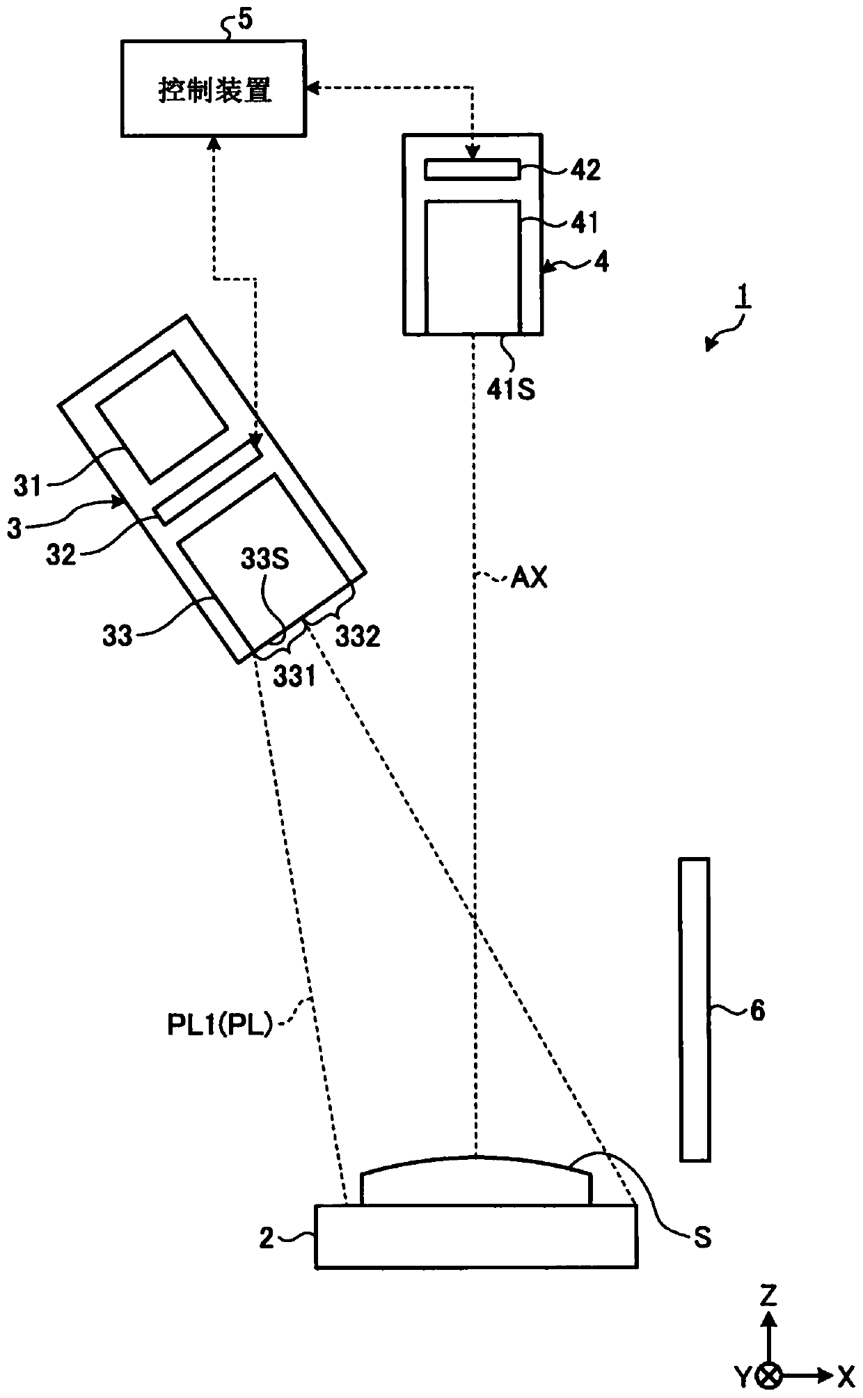
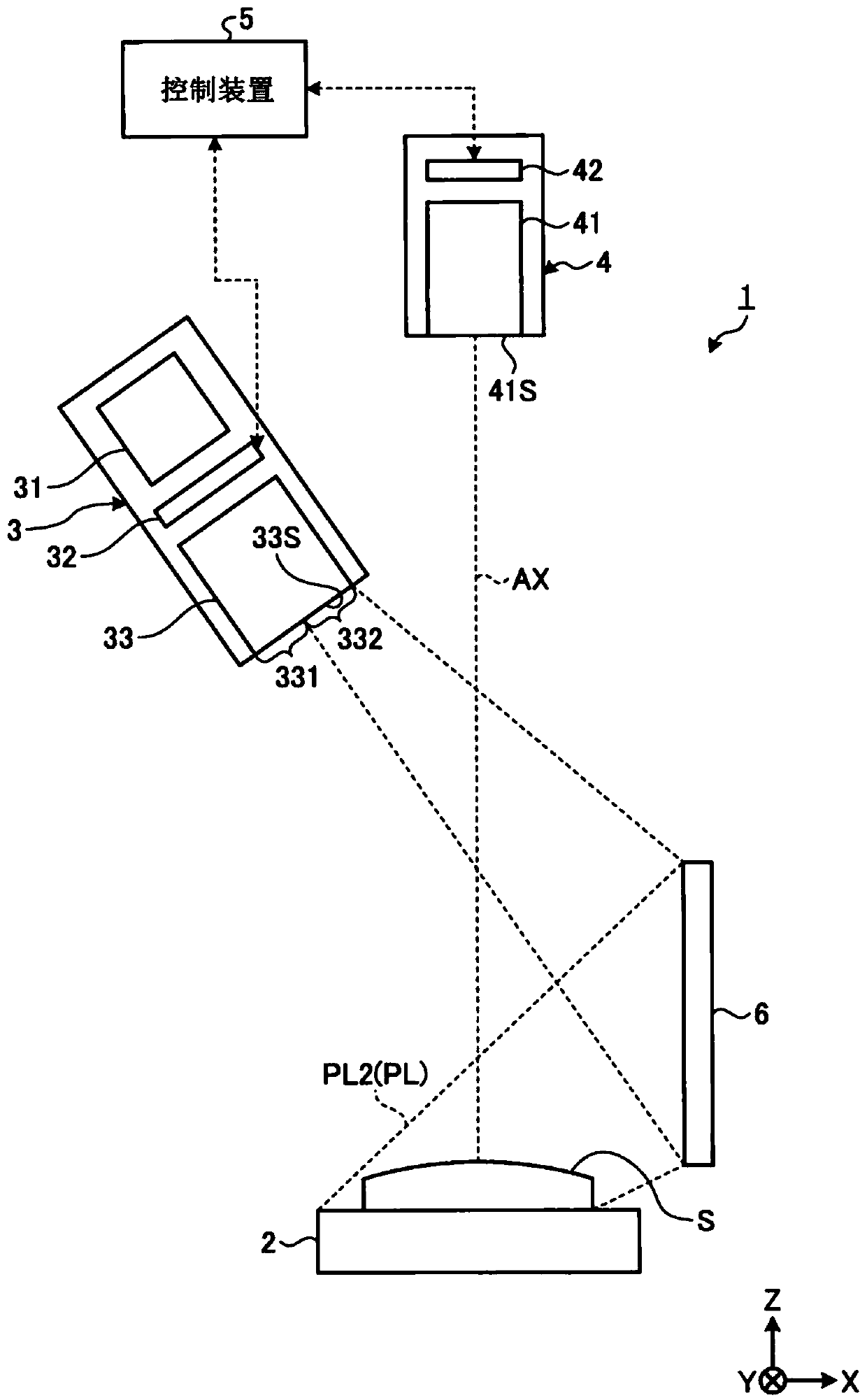
[0023] The first embodiment will be described. figure 1 and figure 2 It is a schematic diagram showing an example of the three-dimensional measurement device 1 according to the present embodiment. Such as figure 1 and figure 2 As shown, the three-dimensional measurement device 1 has: a workbench 2, which supports an object S as a measurement target object; a projection device 3, which emits a pattern light PL; a reflection member 6, which reflects the pattern light PL; an imaging device 4. It acquires image data of the object S irradiated with the pattern light PL; and a control device 5 calculates the three-dimensional shape of the object S based on the image data of the object S acquired by the imaging device 4 .
[0024] The projection device 3 has: a light source 31 that emits light; a light modulation element 32 that optically modulates the light emitted from the light source 31 to generate pattern light PL; and a projection optical system 33 that converts...
no. 2 Embodiment approach
[0061] A second embodiment will be described. In the following description, the same reference numerals are assigned to the same or equivalent components as those of the above-mentioned embodiment, and the description thereof will be simplified or omitted.
[0062] Figure 6 It is a schematic diagram showing an example of the three-dimensional measurement device 1 according to the present embodiment. The three-dimensional measurement device 1 includes a projection device 3 that emits pattern light PL, a reflection member 6 that reflects the pattern light PL, and an imaging device 4 that acquires image data of an object S irradiated with the pattern light PL.
[0063] In the present embodiment, the reflective member 6 includes a first reflective surface 6A, a second reflective surface 6B, and a third reflective surface 6C. Each of the first reflective surface 6A, the second reflective surface 6B, and the third reflective surface 6C is planar. The first reflective surface 6A,...
no. 3 Embodiment approach
[0071] A third embodiment will be described. In the following description, the same reference numerals are assigned to the same or equivalent components as those of the above-mentioned embodiment, and the description thereof will be simplified or omitted.
[0072] Figure 7 It is a schematic diagram which shows an example of the electronic component mounting apparatus 10 which concerns on this embodiment. Such as Figure 7 As shown, the electronic component mounting apparatus 10 has the three-dimensional measuring apparatus 1 described in the above-mentioned embodiment.
[0073] The electronic component mounting apparatus 10 mounts the electronic component C on the board|substrate P. As shown in FIG. The electronic component mounting apparatus 10 has: a mounting head 12 having a suction nozzle 11 for holding the electronic component C; an electronic component supply device 13 for supplying the electronic component C; P for conveyance; and a control device 100 that controls...
PUM
 Abstract
Description
Claims
Application Information