
Rolling diaphragm pump

A technology for diaphragm pumps and diaphragms, applied to pumps, pump components, pump parameters, etc., can solve problems such as high cost and complex structure, and achieve the effect of suppressing cost increase and simple structure

Active Publication Date: 2020-09-04
NIPPON PILLAR PACKING CO LTD
View PDF12 Cites 0 Cited by
  • Summary
  • Abstract
  • Description
  • Claims
  • Application Information

AI Technical Summary

Problems solved by technology

Therefore, there is a problem that the structure is complicated and very costly

Method used


Image

  • Rolling diaphragm pump
  • Rolling diaphragm pump
  • Rolling diaphragm pump

Examples


Embodiment Construction

[0028] Next, preferred embodiments of the present invention will be described with reference to the drawings.

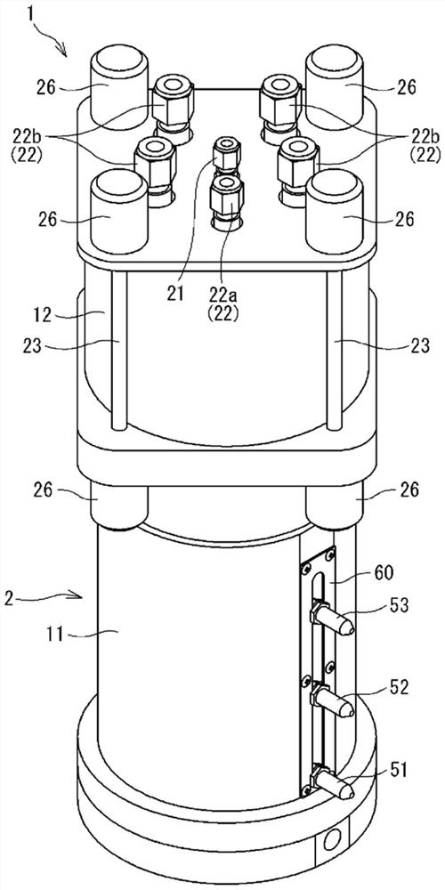
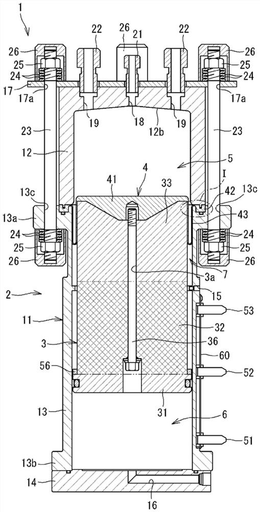
[0029] figure 1 It is a perspective view of the rotary diaphragm pump concerning embodiment of this invention. figure 2 is a sectional view of the rotary diaphragm pump. exist figure 1 and figure 2 Among them, a rotary diaphragm pump 1 has a housing 2 , a piston 3 and a rotary diaphragm 4 . In the present embodiment, the longitudinal direction (axial direction) of the rotary diaphragm pump 1 (hereinafter also simply referred to as the pump 1 ) is arranged in the vertical direction, but it may also be arranged in the horizontal direction.

[0030] [Structure of the case]

[0031] The housing 2 has a cylinder body 11 and a pump head 12 . The cylinder block 11 has: a cylinder main body 13 formed in a cylindrical shape; and a disk-shaped bottom plate 14 fixed to an axial lower end of the cylinder main body 13 . The cylinder main body 13 and the bottom plate 14 a...


PUM


Abstract

Provided is a rolling diaphragm pump in which an increase in cost can be suppressed using a simple configuration. A rolling diaphragm pump 1 is provided with: a housing 2; a piston 3 which is disposedso as to be slidable relative to the inner peripheral surface of the housing 2 and which can reciprocate in an axial direction; a rolling diaphragm 4 having a movable section 41 which is disposed atone axial end of the piston 3 and which can reciprocate with the piston 3, a stationary section 42 which is affixed to the housing 2, and a flexible connection section 43 which connects the movable section 41 and the stationary section 42; a pump chamber 5 which is defined and formed on one axial side in the housing 2 by the rolling diaphragm 4, and the volume of which is changed by the deformation of the connection section 43 caused by the reciprocation of the piston 3, thereby causing the pump chamber 5 to suck in and discharge fluid to be transferred; and an operating fluid chamber 6 whichis defined and formed on the other axial side in the housing 2 by the other axial end of the piston 3, and to and from which operating fluid is supplied and discharged to reciprocate the piston 3.

Description

technical field [0001] The invention relates to a rotary diaphragm pump. Background technique [0002] For example, in the manufacturing processes of semiconductors, liquid crystals, organic EL, solar cells, etc., a rotary diaphragm pump is sometimes used as a pump for feeding the chemical solution when applying or preparing the chemical solution. [0003] For example, as described in Patent Document 1, this type of rotary diaphragm pump changes the volume of the pump chamber (pressure chamber) sealed by the rotary diaphragm in the cylinder by the reciprocating movement of the piston housed in the cylinder, thereby relative to the pump. Inhale the liquid medicine or discharge the liquid medicine indoors. [0004] The piston is connected to a motor as a drive source via a shaft and a ball screw arranged coaxially with the axis thereof. The piston is reciprocated by converting the rotational motion of the motor into linear motion by a ball screw or the like. [0005] Patent...

Claims


Application Information

Patent Timeline
IPC IPC(8): F04B43/06
CPCF04B43/06F04B45/053F04B53/16F04B53/14F05B2210/11F05B2210/12F04B43/067F04B43/0054F04B39/044F04B45/04F04B2201/0201
Inventor 手岛一清浦田大辅
Owner NIPPON PILLAR PACKING CO LTD
Features
  • Generate Ideas
  • Intellectual Property
  • Life Sciences
  • Materials
  • Tech Scout
  • Unparalleled Data Quality
  • Higher Quality Content
  • 60% Fewer Hallucinations
Learn More