Combined type roller for spinning machine drafting mechanism

A combined spinning machine technology, which is applied to spinning machines, drafting equipment, textiles and papermaking, etc., can solve the problems of reducing the number of grinding times and long service life, so as to achieve reduced grinding times, long service life, The effect of prolonging the service life

Inactive Publication Date: 2018-11-13
苏州益垚精密机械有限公司
View PDF0 Cites 2 Cited by
  • Summary
  • Abstract
  • Description
  • Claims
  • Application Information

AI Technical Summary

Problems solved by technology

The invention replaces the original hard connection between the shaft and the bearing by adding a rubber ring between the shaft and the inner sleeve of the bearing. Due to the elasticity of the rubber, the top roller can swing 360 degrees around the shaft, so the top roller can swing around the axis. 360-degree compensation avoids slipping, solves the problem of poor contact between top rollers and rollers, and greatly ensures the quality of spinning; and it adopts a detachable combination design, the overall structure is simple, and can be It is directly installed on the pressure arm and used without fine-tuning, so it is convenient and quick to use, assemble, disassemble and maintain, with low maintenance cost, stable quality, strong implementability, and wide application range; The dust cover well avoids the erosion of dust and impurities, and has a long service life, which reduces the number of grinding times and prolongs the service life

Method used


Image

  • Combined type roller for spinning machine drafting mechanism
  • Combined type roller for spinning machine drafting mechanism

Examples


Embodiment 1

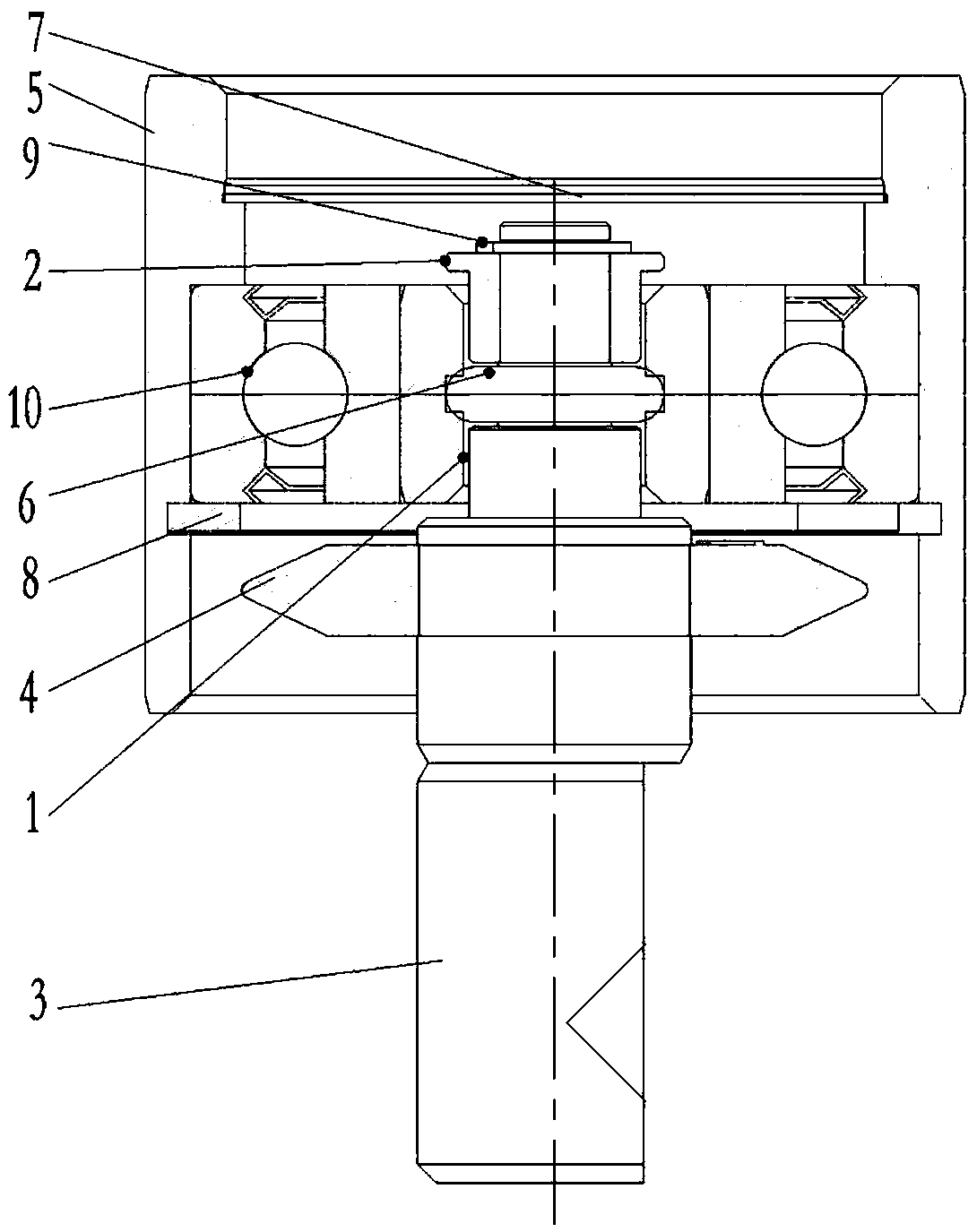
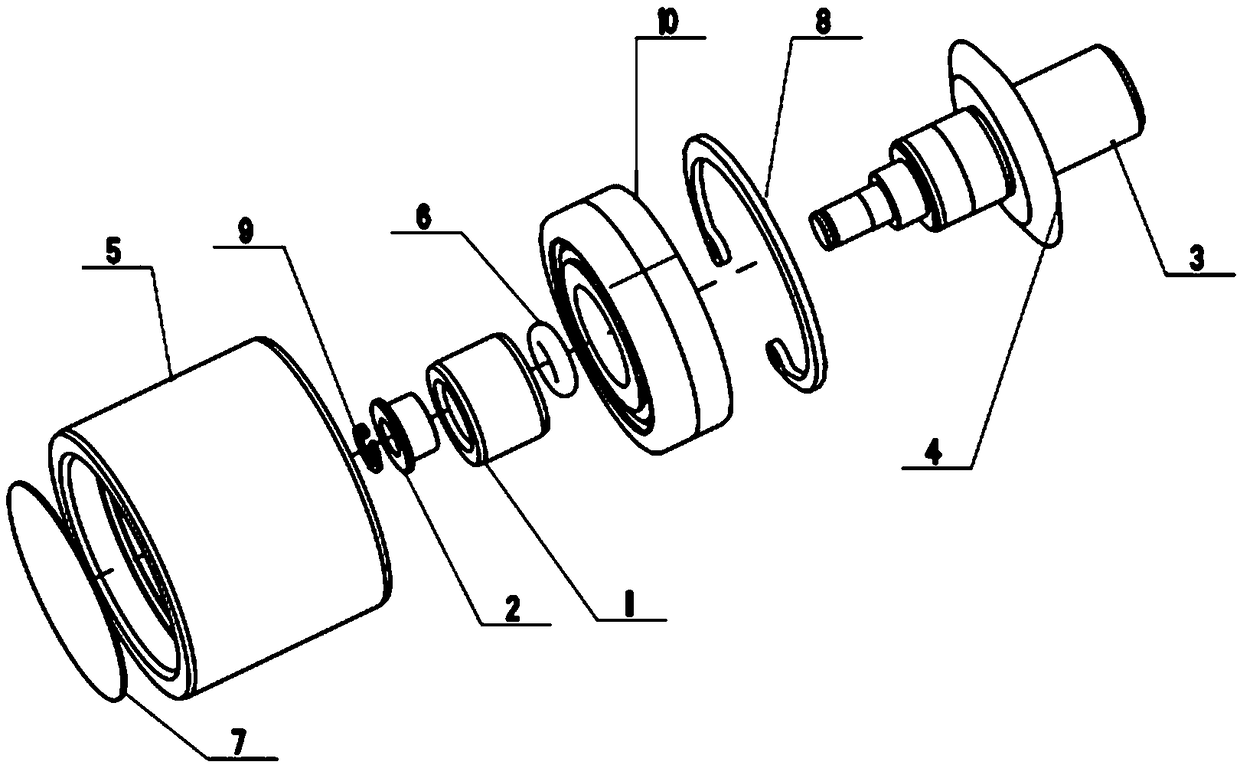
[0026] Such as Figure 1-Figure 2 As shown, a combined top roller for the drafting mechanism of a spinning machine in this embodiment includes a bearing inner sleeve 1, a shaft sleeve 2, a shaft 3, a nylon ring 4, an outer sleeve 5, a rubber ring 6, a dustproof Cover 7, first retaining ring 8, second retaining ring 9 and bearing 10.

[0027] The connection relationship of the above-mentioned components is as follows: the shaft 3 passes through the rubber ring 6 and is sequentially connected with the bearing inner sleeve 1 and the shaft sleeve 2, and the end of the shaft 3 is sleeved with a second retaining ring 9, and the second washer 9 offsets the shaft sleeve 2; the middle part of the shaft 3 is covered with a nylon ring 4, and the lower part of the shaft sleeve 2 is nested inside the bearing inner sleeve 1; the bearing inner sleeve 1 is integrally nested inside the bearing 10, and the The bearing 10 is nested inside the outer casing 5 , and the two ends of the bearing 10 ...

Embodiment 2

[0032] Such as Figure 1-Figure 2 As shown, a combined top roller for the drafting mechanism of a spinning machine in this embodiment includes a bearing inner sleeve 1, a shaft sleeve 2, a shaft 3, a nylon ring 4, an outer sleeve 5, a rubber ring 6, a dustproof Cover 7, first retaining ring 8, second retaining ring 9 and bearing 10.

[0033] The connection relationship of the above-mentioned components is as follows: the shaft 3 passes through the rubber ring 6 and is sequentially connected with the bearing inner sleeve 1 and the shaft sleeve 2, and the end of the shaft 3 is sleeved with a second retaining ring 9, and the second washer 9 offsets the shaft sleeve 2; the middle part of the shaft 3 is covered with a nylon ring 4, and the lower part of the shaft sleeve 2 is nested inside the bearing inner sleeve 1; the bearing inner sleeve 1 is integrally nested inside the bearing 10, and the The bearing 10 is nested inside the outer casing 5 , and the two ends of the bearing 10 ...


PUM


Abstract

The invention discloses a combined type roller for spinning machine drafting mechanism, and mainly relates to the technical field of textile machinery. The roller comprises a bearing inner sleeve, a shaft sleeve, a shaft, an outer sleeve and a bearing; the shaft penetrates through a rubber ring to be cooperatively connected with the bearing inner sleeve and the bearing sleeve in sequence, a secondcheck ring sleeves the end of the shaft, and a second gasket abuts against the shaft sleeve; a nylon ring sleeves the middle of the shaft, and the lower portion of a shaft sleeve is sleeved with theinner side of a bearing inner sleeve; the bearing inner sleeve is integrally nested in the bearing, the bearing is nested in the outer sleeve, and the two ends of the bearing abut against the outer sleeve and a first check ring respectively; a dust cover is clamped in the outer sleeve. The roller can perform enough compensation, the spinning quality is greatly guaranteed, the sealing property is good, the service life is long, and the application range is wide.

Description

technical field [0001] The invention relates to the technical field of textile machinery, in particular to a combined top roller used for a drafting mechanism of a spinning machine. Background technique [0002] Spinning machine is a kind of textile machinery that processes pre-oriented yarns such as polyester and nylon into different varieties and deniers through draft deformation. The drafting mechanism of the spinning machine must have sufficient holding force when drawing the tow. , so that the tow moves forward according to the surface speed of the roller, and minimizes the slipping of the tow in the drafting mechanism. The top roller belongs to the parts of the drafting mechanism, and its function is to press the tow on the roller to improve the holding force of the tow and reduce slippage. [0003] In recent years, with the continuous development of science and technology, related industries have higher and higher technical requirements for spinning machines. However...

Claims


Application Information

Patent Timeline
Patent Type & Authority Applications(China)
IPC IPC(8): D01H5/76D01H5/80D01H5/86
CPCD01H5/76D01H5/80D01H5/86
Inventor 张惠兴
Owner 苏州益垚精密机械有限公司
Why Eureka
Try Eureka