Vehicle passage system for roundabout, and passage control method thereof

A technology of a roundabout and a control method, which is applied in the field of vehicle traffic system and traffic control, can solve the problems of large delay per vehicle and low resource utilization efficiency, reduce the delay per vehicle, solve the failure of secondary parking method, and save space The effect of improving resource utilization efficiency

Active Publication Date: 2018-11-13
HARBIN INST OF TECH
View PDF8 Cites 8 Cited by
  • Summary
  • Abstract
  • Description
  • Claims
  • Application Information

AI Technical Summary

Problems solved by technology

[0004] In order to solve the problems of low space resource utilization efficiency and large average vehicle delay in existi

Method used


Image

  • Vehicle passage system for roundabout, and passage control method thereof
  • Vehicle passage system for roundabout, and passage control method thereof
  • Vehicle passage system for roundabout, and passage control method thereof

Examples


specific Embodiment approach 1

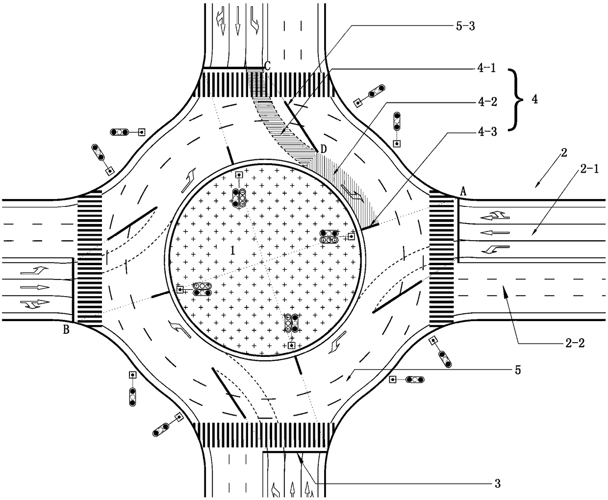
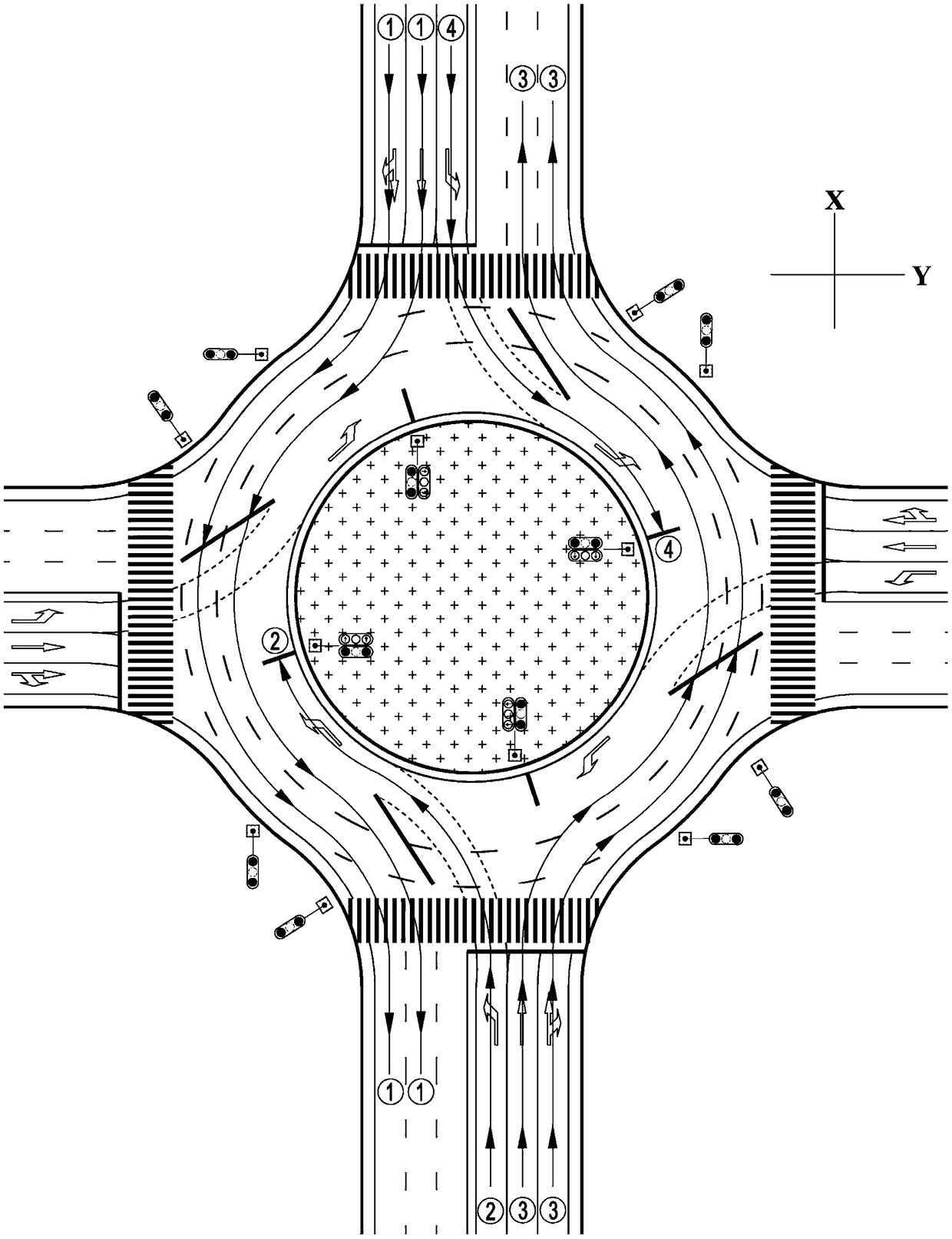
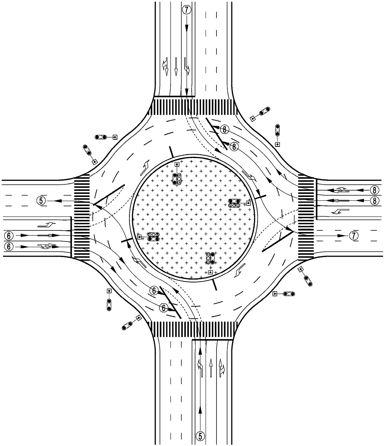
[0035] Specific implementation mode one: combine figure 1 To illustrate this embodiment, a roundabout vehicle traffic system provided in this embodiment includes: a center island 1 located in the center, a ring road surrounding the center island 1, and four intersections connected to the ring road. Road 2 (because most roundabouts are 4 roads, this technical scheme only considers the situation of 4 roads), each said road 2 includes entering the entrance road 2-1 and driving away from the roundabout direction. Exit lanes 2-2 in the direction of the roundabout, wherein each entrance lane 2-1 includes a left-turn lane and a through lane;

[0036] One end of each said entrance road 2-1 connected with the ring road is provided with an entrance road stop line 3, and said entrance road stop line 3 is provided with an entrance road traffic signal light in front of the vehicle advancing direction;

[0037] The ring road includes an inner ring road and an outer ring road;

[0038] A l...

specific Embodiment approach 2

[0048] Specific embodiment 2: The difference between this embodiment and specific embodiment 1 is that in order to avoid traffic conflicts in the roundabout between traffic flows in two directions, each of the straight-going waiting areas 5 and its counterclockwise left turn waiting to turn Zone 4 is disjoint.

[0049] Other steps and parameters are the same as those in the first embodiment.

specific Embodiment approach 3

[0050] Specific embodiment three: the difference between this embodiment and specific embodiment one or two is that in order to ensure that the left-turning vehicle driving from the entrance road into the inner ring road of the roundabout runs smoothly, the left line of the left extension section 4-1 is in line with the inner circle. The outer edge of the ring is tangent.

[0051] Other steps and parameters are the same as those in Embodiment 1 or 2.


PUM


Abstract

The invention provides a vehicle passage system for a roundabout, and a passage control method thereof, and belongs to the field of traffic engineering. According to the vehicle passage system for theroundabout, rotary roads of the roundabout comprise the inner rotary road and the outer rotary road. A left-turn waiting area is arranged between the inner rotary road and a left-turn lane of each entrance lane and comprises a left extending section and an inner overlaying section. A turn waiting area parking line is arranged at the end, connected with the inner rotary road, of each left-turn waiting area. Turn waiting area traffic signal lamps are arranged in front of each turn waiting area parking line. A straight-travelling waiting area is arranged between the outer rotary road and a straight-traveling lane of each entrance lane and comprises a right extending section and an outer overlaying section. A straight-travelling waiting area parking line is arranged at the end, connected withthe inner rotary road, of each straight-travelling waiting area. Travelling waiting area traffic signal lamps are arranged in front of each straight-travelling waiting area parking line. According tothe vehicle passage system for the roundabout, and the passage control method thereof, the problems that an existing roundabout is low in space resource utilization efficiency and large in average traffic delay are solved; and the vehicle passage system for the roundabout, and the passage control method thereof can be used for the roundabout with the large left-turn traffic demand.

Description

technical field [0001] The invention relates to a vehicle passage system and a passage control method, belonging to the field of traffic engineering. Background technique [0002] A roundabout is to set a center island in the center of the intersection, and use a ring road to organize and channelize the traffic, so that all vehicles entering will drive in a one-way direction around the island in a counterclockwise direction (countries or regions that drive on the left are in a clockwise direction). It is a plane crossing that drives out from the island until the desired intersection, commonly known as a turntable. For urban roads with small traffic volumes, roundabouts are an effective way to organize turning traffic. However, with the increasing traffic demand, the limitations of roundabouts have become increasingly prominent. How to improve the traffic efficiency of roundabouts? On the agenda, signal control is one of the methods. At present, the main signal control meth...

Claims


Application Information

Patent Timeline
IPC IPC(8): E01C1/02
CPCE01C1/02
Inventor 蒋贤才金宇冷军强马涛
Owner HARBIN INST OF TECH
Why Eureka
Try Eureka