
A mechanical logic device and method of use

A technology of mechanical logic and spatial location, applied in building locks, buildings, building structures, etc., can solve problems such as overturning, and achieve the effect of strong practical value

Active Publication Date: 2020-05-19
WATER ENG ECOLOGICAL INST CHINESE ACAD OF SCI
View PDF7 Cites 0 Cited by
  • Summary
  • Abstract
  • Description
  • Claims
  • Application Information

AI Technical Summary

Problems solved by technology

The present invention solves the major safety hazards of the multi-drawer cabinet, which is prone to overturning when the drawers are opened at will.

Method used


Image

  • A mechanical logic device and method of use
  • A mechanical logic device and method of use
  • A mechanical logic device and method of use

Examples


Embodiment 1

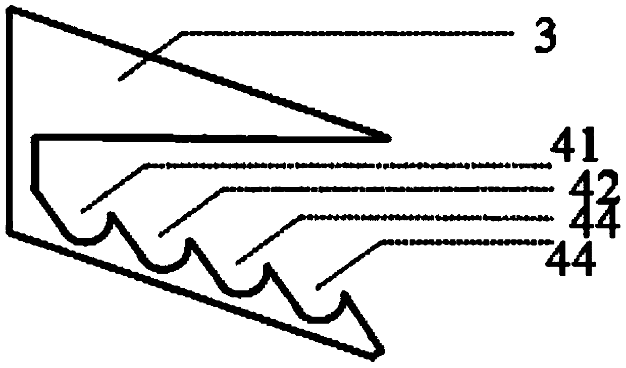
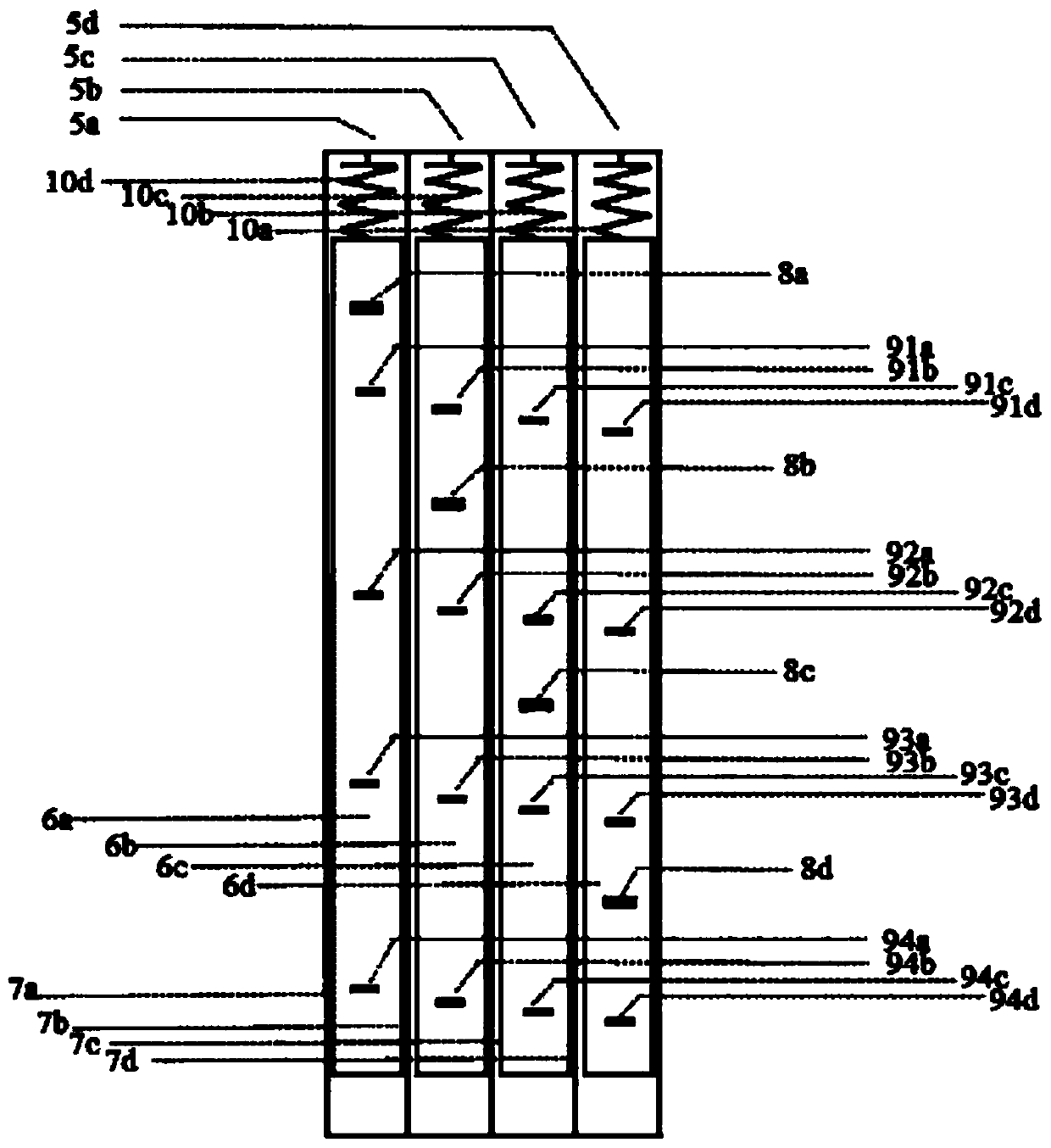
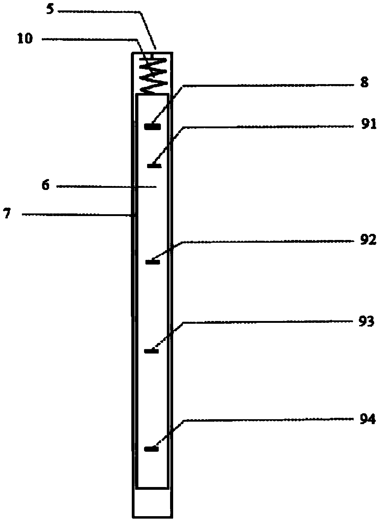
[0038] The present invention will be further described in detail below in conjunction with the accompanying drawings and embodiments. In this embodiment, the chest of drawers to be installed is a 4-drawer chest. according to figure 1 , figure 2 , image 3 , Figure 4 , Figure 5 As shown, a mechanical logic device is composed of a first compound safety lock nose 1a, a second compound safety lock nose 1b, a third compound safety lock nose 1c, a fourth compound safety lock nose 1d, and a compound mechanical logic lock 2; Composite safety lock nose 1 is made up of safety lock bolt 3 and first safety lock nose 41, second safety lock nose 42, third safety lock nose 43, fourth safety lock nose 44; composite mechanical logic lock 2 is composed of first mechanical logic lock nose Lock 5a, the second mechanical logic lock 5b, the third mechanical logic lock 5c, the fourth mechanical logic lock 5d, the safety lock bolt 3 is in the first safety lock nose 41, the second safety lock ...

Embodiment 2

[0044] like Figure 5 As shown, taking the chest of drawers to be installed as an example of a four-drawer chest, a method of using a mechanical logic device, the steps are:

[0045] A. When using the mechanical logic device, select the corresponding combined mechanical logic device according to the drawer cabinet to be installed. Wherein, the quantity of compound safety lock nose, the quantity of the safety lock nose in each compound safety lock nose, the independent mechanical logic lock quantity that compose compound mechanical logic lock, the quantity of bolt in each independent mechanical logic lock are all related to the number to be installed. The chest of drawers has the same number of drawers.

[0046] In this embodiment, the chest of drawers to be installed is a four-drawer chest. A mechanical logic device includes: four composite safety lock noses (1a, 1b, 1c, 1d) and a composite mechanical logic lock 2. Wherein, each composite safety lock nose is composed of a saf...


PUM


Abstract

The invention discloses a mechanical logic device and a using method thereof. The mechanical logic device is composed of a composite safety lock nose, composite mechanical logic lock, safety lock boltand safety lock nose, the safety lock bolt is in a slope shape, a slope is arranged on the slope, the safety lock nose is in a slope shape, a groove is formed in the safety lock nose, the safety lock nose capable of being spliced with one another, the safety lock bolt is arranged right above the safety lock nose which are connected together to form a composite safety lock nose together, the number of the composite safety locking noses and the number of the safety locking noses in each composite safety locking nose, is the same as the number of drawers of the drawer cabinet to be installed. During use, the composite safety lock nose is installed on the same side face of each layer of drawer, the composite mechanical logic lock is installed inside the cabinet body on the side face of the drawer, the space positions of the lock heads and the pins in the composite mechanical logic lock are adjusted, the lock head corresponds to the safety lock bolt, the plug pin corresponds to the safetylock nose, the drawer cabinet can only open one drawer, the problem that the drawer cabinet is turned over due to the fact that the gravity center is moved outwards when a plurality of drawers are opened is effectively avoided.

Description

technical field [0001] The present invention relates to the technical field of mechanical logic devices, more specifically to a mechanical logic device, and also to a method for using the mechanical logic device. The scope of application includes improving the safety performance of drawer cabinets, experiment cabinets, filing cabinets, and lockers. Background technique [0002] In recent years, many kinds of cabinets with drawers have a fatal problem: when multiple drawers are opened at the same time or used improperly, they will fall over due to unstable center of gravity. Especially when rummaging through the drawers due to strong curiosity, so the above-mentioned problems occur repeatedly. For example, since a certain manufacturer’s chest of drawers was launched in 1999, the global holdings have exceeded 65 million. However, it has a fatal design flaw: when multiple drawers are opened at the same time, the center of gravity of the cabinet is unstable and easy to fall over...

Claims


Application Information

Patent Timeline
Patent Type & Authority Patents(China)
IPC IPC(8): E05B65/463E05B15/10E05B15/00
CPCE05B15/00E05B15/10E05B65/463
Inventor 沈强李嗣新米玮杰郑金秀董方勇陈明秀
Owner WATER ENG ECOLOGICAL INST CHINESE ACAD OF SCI
Learn More