Diesel vehicle low emission control device and method

A control method and technology of a control device, which are applied to exhaust devices, electronic control of exhaust treatment devices, and diagnostic devices of exhaust treatment devices, etc., can solve problems such as high requirements for chassis layout, high fuel consumption, and deterioration of emissions. , to achieve the effect of reducing the workload of calibration and development, reducing fuel consumption and increasing exhaust temperature

Active Publication Date: 2018-11-13
SAIC MOTOR
View PDF8 Cites 13 Cited by
  • Summary
  • Abstract
  • Description
  • Claims
  • Application Information

AI Technical Summary

Problems solved by technology

[0003] With the upgrading of emission standards, the main solutions are concentrated on post-treatment. The typical post-treatment configuration is DOC+cDPF+SCR (wherein, DOC: Disel oxidation catalyst, that is, oxidation catalyst, is mainly used to treat HC and CO DPF: Disel particle filter, that is, diesel particulate filter, mainly used to treat PM emissions, can be divided into DPF and cDPF according to whether the surface of the filter element is coated with catalyst; SCR: selectedcatalystic reduction, that is, selected Reduction, mainly used to deal with NOx emissions), but whether it is DPF regeneration or SCR to deal with NOx, there is a minimum requirement for temperature. The traditional method is to use the post-treatment close-coupled installation method, which requires a lot of chassis layout. High, some are arranged in the engine compartment, which brings a severe test to the thermal management of the engine compartment; for the DPF regeneration, the traditional method is to use the post-injection technology of the engine to burn a part of the fuel in the DPF again to increase the temperature and burn the particles This method brings a lot of calibration development workload, and at the same time brings about emission deterioration, high fuel consumption, and oil dilution

Method used


Image

  • Diesel vehicle low emission control device and method
  • Diesel vehicle low emission control device and method
  • Diesel vehicle low emission control device and method

Examples


Embodiment 1

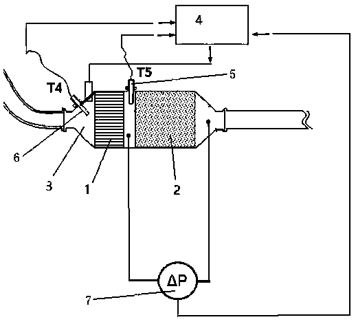
[0058] According to the signals of the exhaust temperature sensors 5, 6 and the differential pressure sensor 7, etc., the electronic control unit 4 (DCU) is input, and the DCU judges whether the engine is in a cold start, whether the selective reduction (SCR) needs auxiliary heating, and whether the PM particles need to be passive. Regeneration, whether the PM particles need to be actively regenerated, so that the DCU controls the electric heating device 3 to conduct electric heating on the exhaust gas.

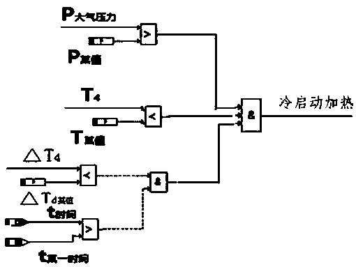
[0059] When the diesel engine is in a cold start state, that is:

[0060] i) The pressure P of the atmosphere 大气 Greater than 0.76 P 大气 ;

[0061] ii) The current temperature T of the oxidation catalyst 1 4 Less than 180°C;

[0062] iii) Over a period of time T 时间 less than 5 seconds, T 4 The change value of △T 4 less than 1°C;

[0063] The electronic control device 4 controls the electric heating device 3 to perform cold start heating according to its own logic or th...


PUM


Abstract

The invention discloses a diesel vehicle low emission control device and method. The diesel vehicle low emission control device comprises an oxidation catalyst (1), a diesel particle catcher (2), a first exhaust temperature sensor (6), a second exhaust temperature sensor (5), an electric heating device (3), a differential pressure sensor (7) and an electronic control device (4). The oxidation catalyst is integrated with an electric heating wire of the electric heating device and encapsulated and formed with the diesel particle catcher, the first exhaust temperature sensor is installed at the front end of the oxidation catalyst, and the second exhaust temperature sensor is installed between the oxidation catalyst and the diesel particle catcher. The differential pressure sensor is connectedto the two ends of the diesel particle catcher. The first exhaust temperature sensor, the second exhaust temperature sensor and the differential pressure sensor are connected with the electronic control device. According to the diesel vehicle low emission control device and the method, the exhaust temperature can be raised, the conversion rate of NOX, HC and CO is improved at the low temperatureafter treatment, regeneration of PM particles is controlled, and the purposes of reducing energy consumption and calibrating the development work amount are realized.

Description

technical field [0001] The invention relates to the field of automobile emission control, in particular to a low-emission control device and method for diesel vehicles. Background technique [0002] With the promulgation and implementation of the most stringent national 6B emission regulations in history, major OEMs are facing the upgrade and elimination of old products and the development of new products. [0003] With the upgrading of emission standards, the main solutions are concentrated on post-treatment. The typical post-treatment configuration is DOC+cDPF+SCR (wherein, DOC: Disel oxidation catalyst, that is, oxidation catalyst, is mainly used to treat HC and CO DPF: Disel particle filter, that is, diesel particulate filter, mainly used to treat PM emissions, can be divided into DPF and cDPF according to whether the surface of the filter element is coated with catalyst; SCR: selectedcatalystic reduction, that is, selected Reduction, mainly used to deal with NOx emissi...

Claims


Application Information

Patent Timeline
Patent Type & Authority Applications(China)
IPC IPC(8): F01N3/027F01N3/20F01N11/00F01N13/00
CPCF01N3/027F01N3/2013F01N11/002F01N13/00Y02T10/40Y02A50/20
Inventor 高朝辉高柏濬张立峰程伟民杨双宾于化龙黄亮
Owner SAIC MOTOR
Why Eureka
Try Eureka