Backflush explosion-proof flow cut-off valve group

A technology for cutting off valves and flow, which is applied in the direction of fluid pressure actuation devices, fluid pressure actuation system safety, mechanical equipment, etc. The effect of flushing injection and preventing secondary accidents

Pending Publication Date: 2018-11-13
油威力液压科技股份有限公司
View PDF2 Cites 0 Cited by
  • Summary
  • Abstract
  • Description
  • Claims
  • Application Information

AI Technical Summary

Problems solved by technology

[0004] The above-mentioned prior art relies on external electromagnetic or electric signal valves to close the valve. When a fault occurs in a pipeline of a high-pressure, super-large-flow liquid medium, such as a fracture or a loose flange, the instantaneous pressure and flow energy generated is huge, and the electric control The valve operation cannot respond in time, causing serious accidents

Method used


Image

  • Backflush explosion-proof flow cut-off valve group

Examples


Embodiment 1

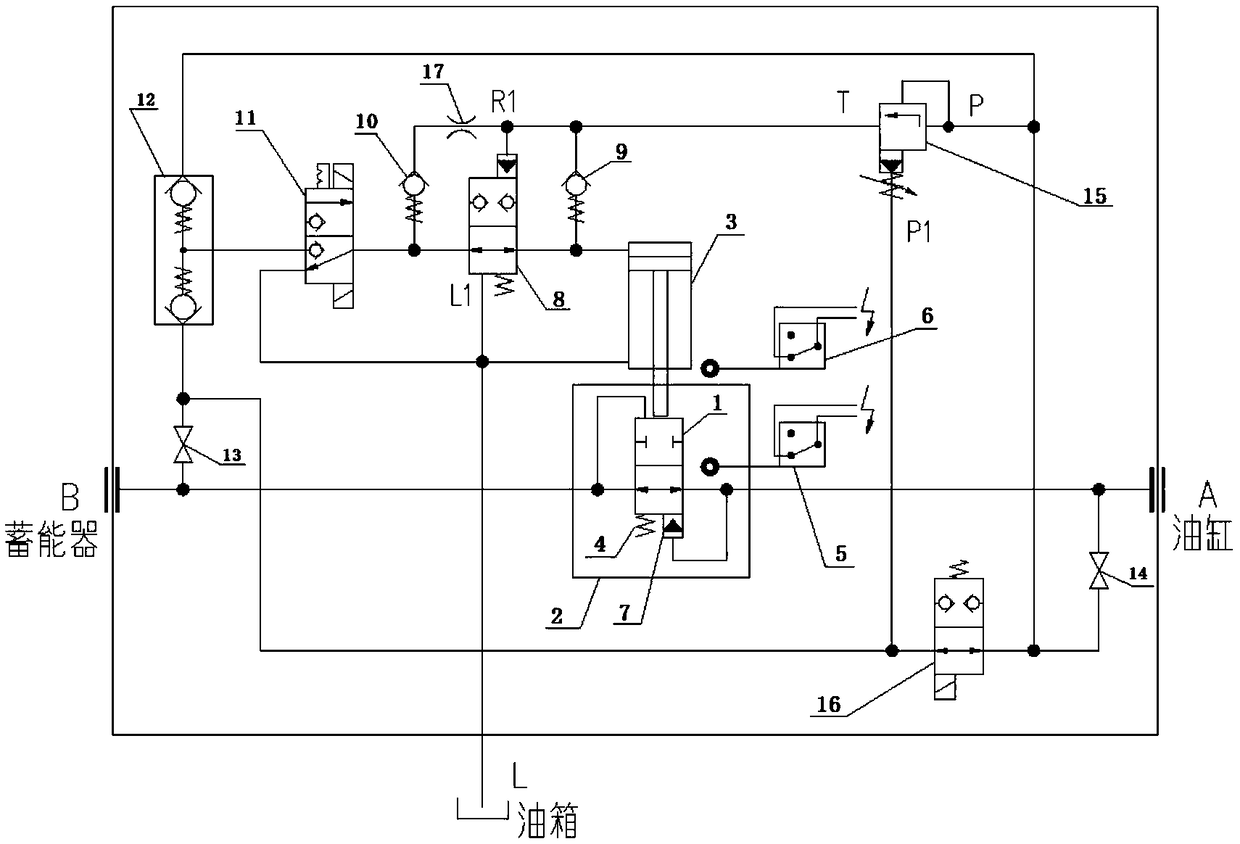
[0036] Such as figure 1 As shown, a recoil explosion-proof flow cut-off valve group includes a forced control mechanism connected between accumulator B and oil cylinder A, a differential pressure sensing control mechanism, a forced cylinder control mechanism, and a restart control mechanism; the forced control mechanism includes a main Spool 1, valve body 2, forced cylinder 3, differential pressure spring 4, spool proximity switch 5, forced cylinder proximity switch 6, blockage 7; differential pressure sensing control mechanism includes double one-way valve 12, stop valve I 13, differential pressure Compensation valve 15; forced cylinder control mechanism includes hydraulic valve 8, check valve I9, check valve II10, solenoid valve I11; restart control mechanism includes cut-off valve II14, solenoid valve II16; accumulator B and oil cylinder A pass through the pipeline Connect the main spool 1, the main spool 1 is in the form of a slide valve, a push rod is provided in the forc...

Embodiment 2

[0048] Such as figure 1 As shown, a recoil explosion-proof flow cut-off valve group includes a forced control mechanism connected between accumulator B and oil cylinder A, a differential pressure sensing control mechanism, a forced cylinder control mechanism, and a restart control mechanism; the forced control mechanism includes a main Spool 1, valve body 2, forced cylinder 3, differential pressure spring 4, spool proximity switch 5, forced cylinder proximity switch 6, blockage 7; differential pressure sensing control mechanism includes double one-way valve 12, stop valve I 13, differential pressure Compensation valve 15; forced cylinder control mechanism includes hydraulic valve 8, check valve I9, check valve II10, solenoid valve I11; restart control mechanism includes cut-off valve II14, solenoid valve II16; accumulator B and oil cylinder A pass through the pipeline Connect the main spool 1, the main spool 1 is in the form of a slide valve, a push rod is provided in the forc...


PUM


Abstract

The invention provides a backflush explosion-proof flow cut-off valve group. The backflush explosion-proof flow cut-off valve group is characterized by comprising a forced control mechanism connectedbetween an energy accumulator and an oil cylinder, a pressure difference induction control mechanism, a forced cylinder control mechanism, and a restart control mechanism, wherein the forced control mechanism comprises a main valve element, a valve body, a forced cylinder, a pressure difference spring, a valve element proximity switch, a forced cylinder proximity switch and a plug; the pressure difference induction control mechanism comprises double check valves, a stop valve I and a pressure difference compensation valve; the forced cylinder control mechanism comprises a hydraulic valve, a check valve I, a check valve II and an electromagnetic valve I; and the restart control mechanism comprises a stop valve II and an electromagnetic valve II. According to the backflush explosion-proof flow cut-off valve group, an external power source is not needed, and the valve group is instantaneously closed by virtue of the own pressure difference, almost without time lag; and the backflush explosion-proof flow cut-off valve group is sensitive in reaction, high in feedback efficiency, and especially suitable for a control occasion with a high pressure and an ultra-high flow.

Description

technical field [0001] The invention relates to the technical field of flow valves, in particular to a high-pressure ultra-large flow recoil explosion-proof flow cut-off valve group. Background technique [0002] The recoil explosion-proof flow cut-off valve group is an important component to solve the safety of the high pressure and large flow accumulator load hydraulic system. In the past, this technology was blank in China. This product is especially suitable for the wave compensation hydraulic system of the offshore drilling platform. In the recoil explosion-proof automatic mode, the valve group mainly plays the role of flow cut-off or cut-off. In the event of failures such as pipeline rupture or flange disconnection, due to the large amount of energy stored in the pressurized gas cylinders of the accumulator group in the oil supply system, its output flow will be accelerated instantaneously. If the transmission of the pipeline medium is not cut off in time, the accumul...

Claims


Application Information

Patent Timeline
IPC IPC(8): F15B20/00
CPCF15B20/00F15B20/005
Inventor 林广季作强
Owner 油威力液压科技股份有限公司
Why Eureka
Try Eureka