
A cage and a double row or multiple row cylinder roller bearing with the cage

A cylindrical roller bearing and cage technology, which is applied to shafts and bearings, bearing components, mechanical equipment, etc., can solve the problems of complex processing and high cage cost, and achieve the effects of simplifying processing, increasing rated load and reducing costs.

Inactive Publication Date: 2018-11-13
SCHAEFFLER TECH AG & CO KG
View PDF0 Cites 0 Cited by
  • Summary
  • Abstract
  • Description
  • Claims
  • Application Information

AI Technical Summary

Problems solved by technology

Therefore, the cost of the cage is high and the processing is complicated

Method used


Image

  • A cage and a double row or multiple row cylinder roller bearing with the cage
  • A cage and a double row or multiple row cylinder roller bearing with the cage
  • A cage and a double row or multiple row cylinder roller bearing with the cage

Examples


Embodiment Construction

[0032] Exemplary embodiments of the present invention are described below with reference to the accompanying drawings. It should be understood that these specific descriptions are only used to teach those skilled in the art how to implement the present invention, but are not intended to exhaust all possible ways of the present invention, nor are they intended to limit the scope of the present invention.

[0033] In the following description, the axial direction refers to the axial direction of double-row or multi-row cylindrical roller bearings (sometimes simply referred to as "bearing"), which is consistent with the axial direction of the cage and outer ring; the direction perpendicular to the axial direction Called the radial direction; the direction around the axial direction is called the circumferential direction.

[0034] First, refer to Figure 4 to Figure 7 A specific structure of a cage and a bearing according to an embodiment of the present invention will be describ...


PUM


Abstract

The invention provides a cage with low cost and simple processing and used for a double row or multiple row cylinder roller bearing and the double row or multiple row cylinder roller bearing with thecage. The cage includes an annular main part and a plurality of fork parts. Each of the multiple fork parts extends from the axial end face of the main part to the axial outside. The multiple fork parts are arranged spaced apart from each other along a circumferential direction of the main part. Each of the multiple fork parts can be inserted into a hollow part of a corresponding roller so as to enable the cage to be guided by the rollers while holding the rollers.

Description

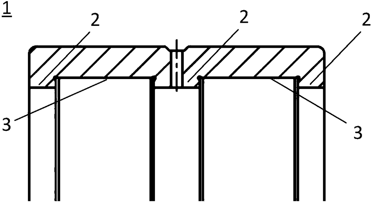
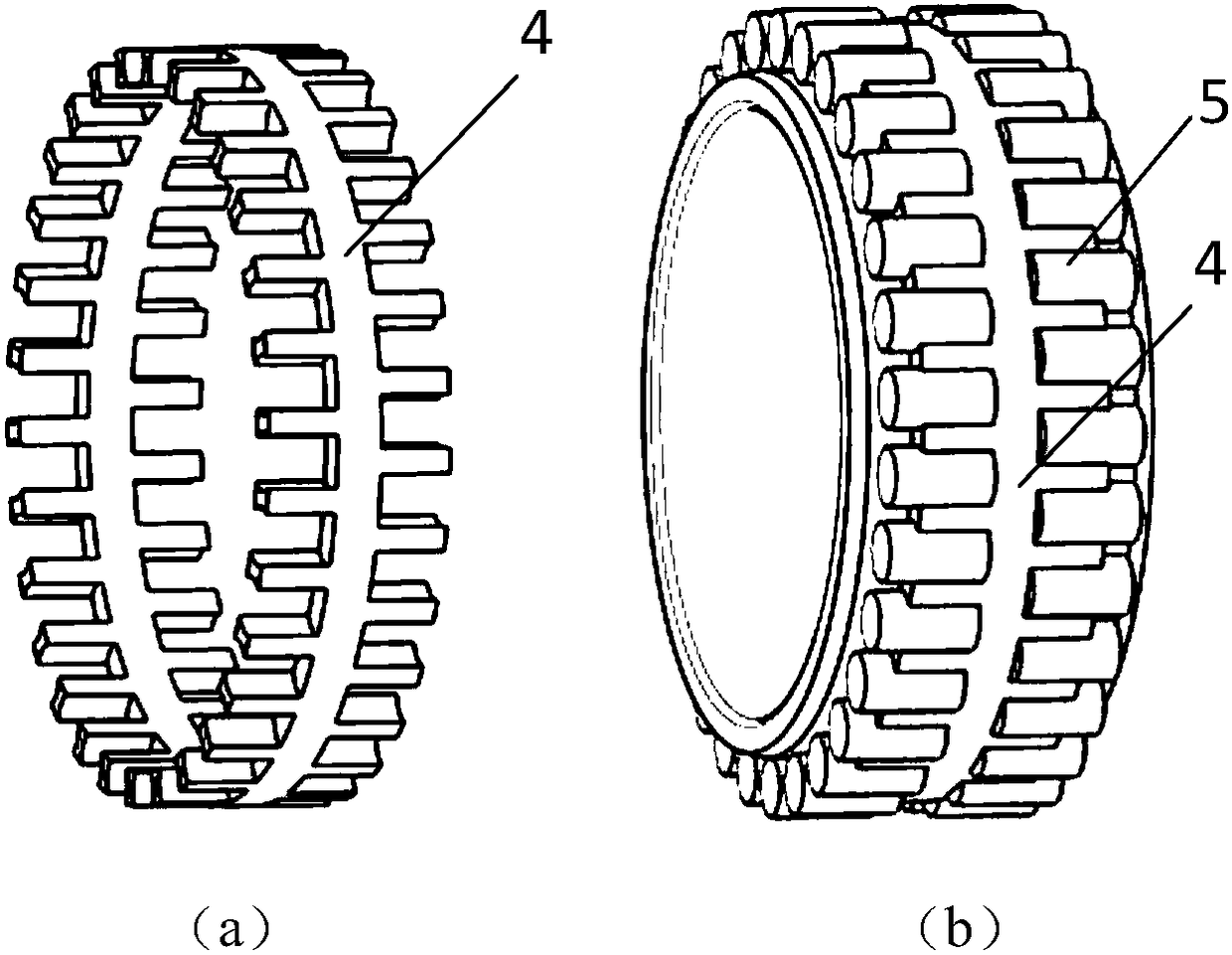
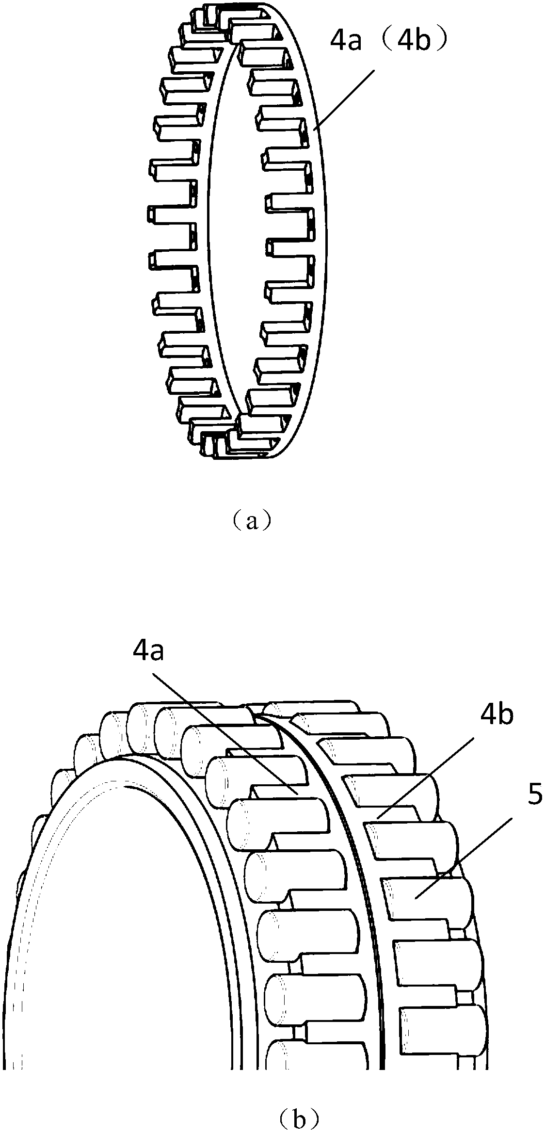
technical field [0001] The present invention relates to a cage of a bearing and the bearing, in particular to a cage for a double-row or multi-row cylindrical roller bearing and a double-row or multi-row cylindrical roller bearing with the cage. Background technique [0002] Such as figure 1 with figure 2 As shown, for a double-row cylindrical roller bearing with three ribs 2 and two raceways 3 on the outer ring 1, a double-fork cage 4 made of brass is currently used to separate the rolling elements 5. The left and right forks of this cage 4 are offset relative to each other in the circumferential direction. [0003] Such as image 3 Another cage made of brass used in this cylindrical roller bearing is shown as two separate single-pronged cages 4a, 4b. In the cylindrical roller bearing, the left single-pronged cage 4a and the right-side single-pronged cage 4b ​​are arranged back-to-back to each other and are displaced relative to each other in the circumferential direct...

Claims


Application Information

Patent Timeline
IPC IPC(8): F16C33/48F16C33/49
CPCF16C33/48F16C33/49
Inventor 刘彩芬
Owner SCHAEFFLER TECH AG & CO KG
Learn More