Speed reducer lubrication discharge pipe structure

A reducer and tube structure technology, which is applied in the direction of gear lubrication/cooling, mechanical equipment, transmission parts, etc., can solve the problems of lubrication pump damage, flow pressure relief, affecting the effect of reducer bearings and gear lubrication, etc., to achieve the use of Long life and good effect

Active Publication Date: 2018-11-13
WORLD TRANSMISSION TECH TIANJIN SHARE LTD
View PDF7 Cites 68 Cited by
  • Summary
  • Abstract
  • Description
  • Claims
  • Application Information

AI Technical Summary

Problems solved by technology

[0002] During the operation of a large reducer, the external cooling system is indispensable to cool the reducer. The cooling power of the cooling system corresponds to the lubricating oil displacement of the lubricating pump. The large reducer has a large operating power and needs to be cooled. Large, the lubricating oil displacement of the corresponding lubricating pump is large enough. Af

Method used


Image

  • Speed reducer lubrication discharge pipe structure
  • Speed reducer lubrication discharge pipe structure

Examples


Embodiment Construction

[0013] Below in conjunction with accompanying drawing and embodiment the present invention will be further described:

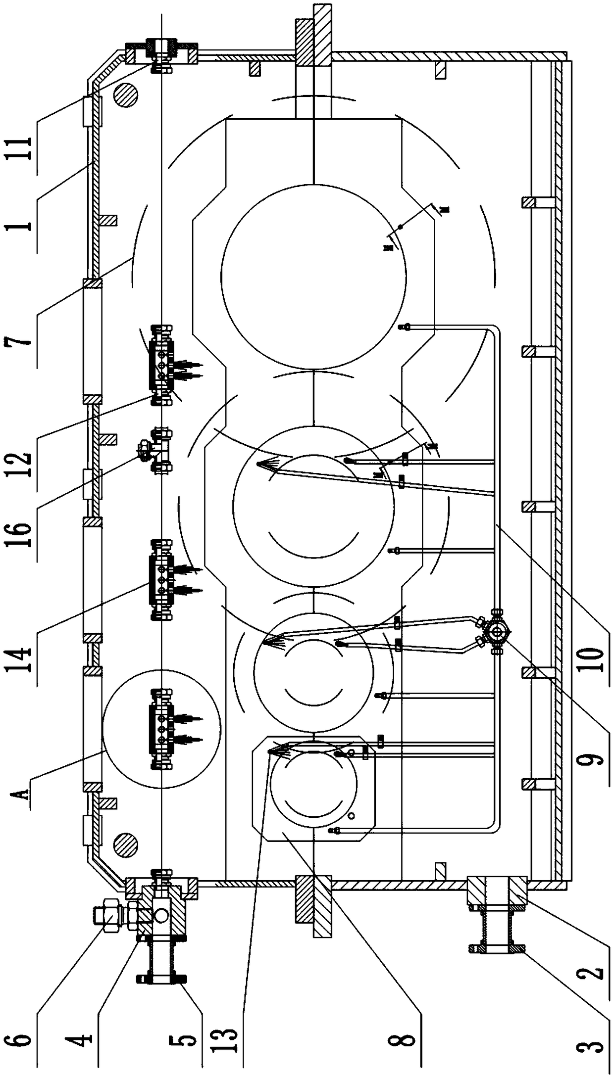
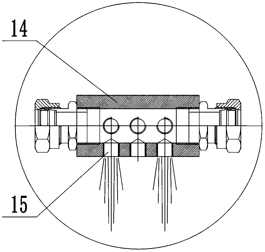
[0014] like figure 1 , 2 As shown, a reducer lubricating pipe structure, including a reducer case 1, is characterized in that an oil outlet pipe 2 is provided at the lower part of one side of the reducer case 1, and the other end of the oil outlet pipe 2 is connected with a lower flange 3. The flange 3 is connected to the oil suction hose for external lubrication, and the upper part of the reducer box 1 on the same side as the lower flange 3 is provided with an oil inlet pipe 4, and the other end of the oil inlet pipe 4 is connected to an upper flange 5, which is connected to the external lubrication The oil supply hose is connected, the upper end of the oil inlet pipe 4 is connected with a double outer wire ferrule joint 6, and the main distributor 9 is arranged under the several reducer gears 7 and several bearing chambers 8 in the reducer casing 1, and th...


PUM


Abstract

The invention discloses a speed reducer lubrication discharge pipe structure. The speed reducer lubrication discharge pipe structure comprises a speed reducer box; an oil outlet pipe is arranged at the lower part of one side of the speed reducer box; a main distributor is arranged under multiple speed reducer gears and multiple bearing cavities in the speed reducer box; multiple oil outlets are formed in the main distributor; the oil outlets of the main distributor are connected with oil supply branch pipes; multiple secondary distributors are transversely arranged above the engaged places ofeach pair of speed reducer gears; the secondary distributors near an oil inlet pipe communicate with the oil inlet pipe through oil pipes; and the secondary distributors far from the oil inlet pipe are connected with first clamping joints. The oil supply branch pipes positioned in the bearing cavities of a speed reducer fully lubricate bearings of the speed reducer through a point-to-point arrangement form; the oil supply branch pipes in the engaged places of gears of the speed reducer lubricate the gears of the speed reducer; damping holes in the secondary distributors reduce the pressure ofredundant lubricating oil pumped by a lubricating pump; and during reducing of the pressure, the gears of the speed reducer are lubricated again, so that the lubricating effect of the bearings and thegears of the speed reducer is excellent, and the service life of a lubricating pump is long.

Description

technical field [0001] The invention relates to the technical field of reducers, in particular to a lubricating pipe arrangement structure of a reducer. Background technique [0002] During the operation of a large reducer, the external cooling system is indispensable to cool the reducer. The cooling power of the cooling system corresponds to the lubricating oil displacement of the lubricating pump. The large reducer has a large operating power and needs to be cooled. Large, the lubricating oil displacement of the corresponding lubricating pump is large enough. After a part of the lubricating oil of the lubricating pump lubricates the bearings and gear meshes in the reducer, most of the flow still needs to be relieved. If the lubricating pump is not relieved, It is easy to cause damage to the lubricating pump and affect the effect of lubricating the bearings and gears of the reducer. At the same time, it is easy to cause damage to the lubricating pump. Contents of the inve...

Claims


Application Information

Patent Timeline
IPC IPC(8): F16H57/04
CPCF16H57/0423F16H57/0435
Inventor 胡炜
Owner WORLD TRANSMISSION TECH TIANJIN SHARE LTD
Why Eureka
Try Eureka