Efficient heat exchange tube for condensation
A heat exchange tube and high-efficiency technology, applied in the field of heat exchange, can solve the problems of low heat exchange efficiency, poor heat exchange performance, and small heat exchange area of heat exchange tubes, so as to improve heat exchange efficiency, increase liquid discharge speed, increase The effect of the heat transfer area
- Summary
- Abstract
- Description
- Claims
- Application Information
AI Technical Summary
Problems solved by technology
Method used
Image

Examples
Embodiment 1
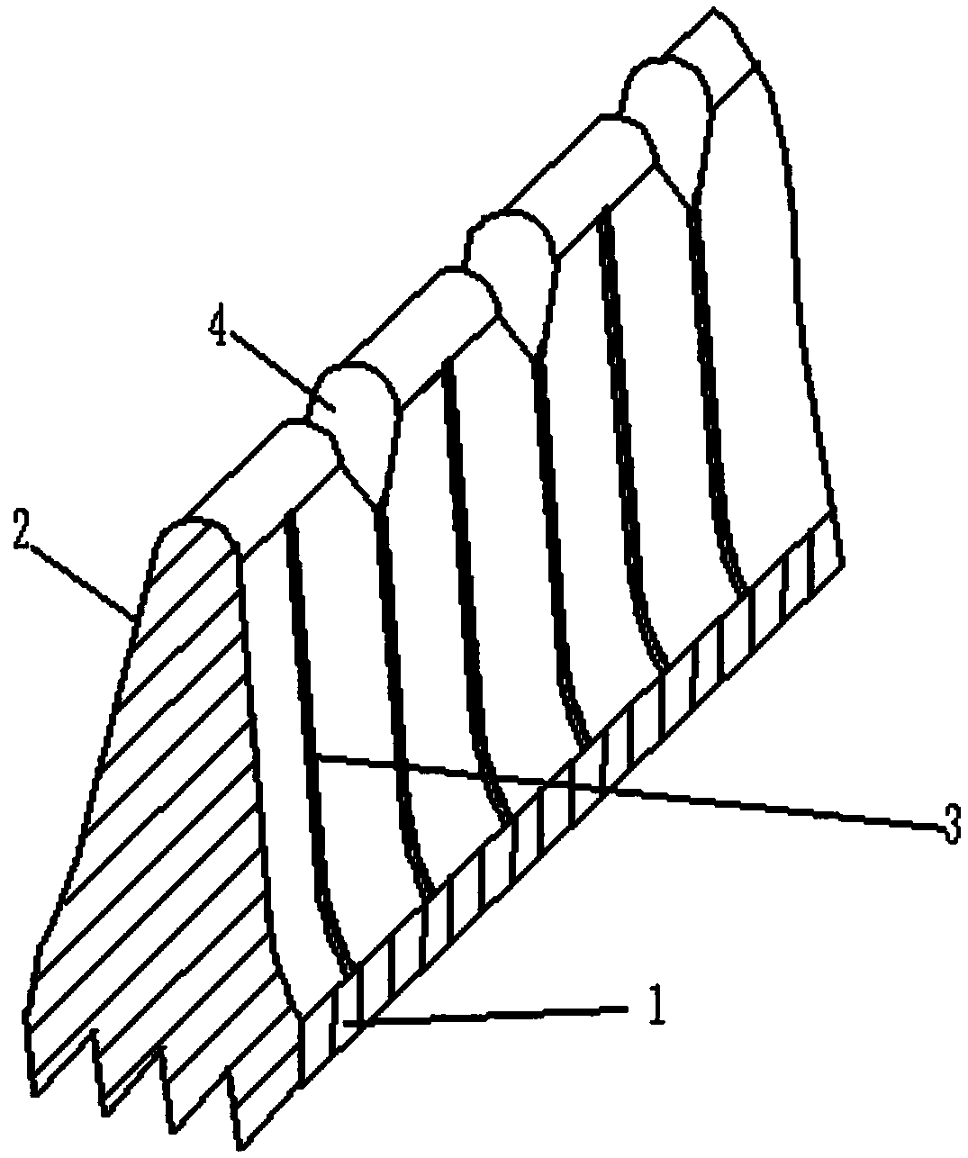
[0020] Such as figure 1 As shown, this embodiment provides a high-efficiency heat exchange tube for condensation, which includes a heat exchange tube body 1 and a plurality of outer fins 2 .
[0021] Specifically, the inner surface of the heat exchange tube body 1 is provided with internal threads; the plurality of outer fins 2 are spiral and evenly distributed on the outer surface of the heat exchange tube body 1 . At the same time, the side of the outer fin 2 is provided with a first groove 3 extending to the root of the outer fin 2, and the top of the outer fin 2 is provided with a second groove 4, the first groove 3, the second groove 4 A channel favorable for liquid flow is formed with the outer surface of the heat exchange tube body 1 .
[0022] In this embodiment, the first groove 3 allows the condensed refrigerant liquid to quickly and smoothly flow to the bottom of the outer fin 2 , which greatly improves the liquid drainage speed on the surface of the heat exchange ...
Embodiment 2
[0029] This embodiment provides another high-efficiency heat exchange tube for condensation, which is basically the same as Embodiment 1, and only the different parts will be introduced below.
[0030] In this embodiment, the height of the outer fin 2 is 0.75-1.1mm; the depth of the first groove 3 is 0.05-0.2mm, the width is 0.05-0.2mm, and the number of the first groove 3 is 75-200 / week; the depth of the second groove 4 is 0.1-0.3mm, the width is 0.1-0.3mm, the number of the second groove 4 is 20-75 / week; the height of the inner tooth 5 is 0.25-0.45mm, The helix angle is 35-60 degrees. It should be noted that if the height of the outer fins 2 is too large or too small, and the distance between the outer fins 2 is too large or too small, the heat transfer performance will be deteriorated.
[0031] In summary, this not only greatly increases the liquid discharge speed of the outer fins 2, but also significantly increases the heat exchange area of the heat exchange tube b...
PUM
| Property | Measurement | Unit |
|---|---|---|
| Height | aaaaa | aaaaa |
| Depth | aaaaa | aaaaa |
| Width | aaaaa | aaaaa |
Abstract
Description
Claims
Application Information
 - Generate Ideas
- Intellectual Property
- Life Sciences
- Materials
- Tech Scout
- Unparalleled Data Quality
- Higher Quality Content
- 60% Fewer Hallucinations
Browse by: Latest US Patents, China's latest patents, Technical Efficacy Thesaurus, Application Domain, Technology Topic, Popular Technical Reports.
© 2025 PatSnap. All rights reserved.Legal|Privacy policy|Modern Slavery Act Transparency Statement|Sitemap|About US| Contact US: help@patsnap.com