
Separate target position test device and test method

A technology of target position and testing device, applied in the direction of target, target indication system, attack equipment, etc., can solve the problems of inability to accurately match and identify multiple targets, large error of test coordinates, and missed detection.

Active Publication Date: 2018-11-13
XIAN TECHNOLOGICAL UNIV
View PDF4 Cites 9 Cited by
  • Summary
  • Abstract
  • Description
  • Claims
  • Application Information

AI Technical Summary

Problems solved by technology

The four-light curtain intersection test system mainly uses four sky-curtain targets or four light-curtain targets as the main body, which can obtain the speed and position parameters of a single target, and requires that the target must pass through the light curtain vertically, otherwise the test coordinate error is large, and the target needs to be tested. Parameter correction; the six light curtain intersection test system mainly uses six sky curtain targets or six light curtain targets as the main body, and can obtain parameters such as single target flight speed, azimuth angle, and vertical target coordinates; the CCD intersection test system uses multiple CCD Cameras intersect to form a detection target surface, which has a complex structure and cannot accurately control the coincidence of multiple surfaces, and at the same time cannot accurately obtain the intersection angle, resulting in low accuracy of measurement target parameters and missed measurements
These test systems can realize the test of single target parameters, and can also realize the multi-target test under low-frequency target continuous shooting, but when high-frequency multi-target continuous shooting, multiple targets have diversity and randomness during flight, When passing through the detection area, there are situations of occlusion, overlap, and simultaneous arrival at the same detection light curtain. At this time, the test system cannot accurately match and identify multiple targets fired in high-speed bursts, nor can it measure the speed, position and other parameters corresponding to multiple targets with high precision.

Method used


Image

  • Separate target position test device and test method
  • Separate target position test device and test method
  • Separate target position test device and test method

Examples


Embodiment Construction

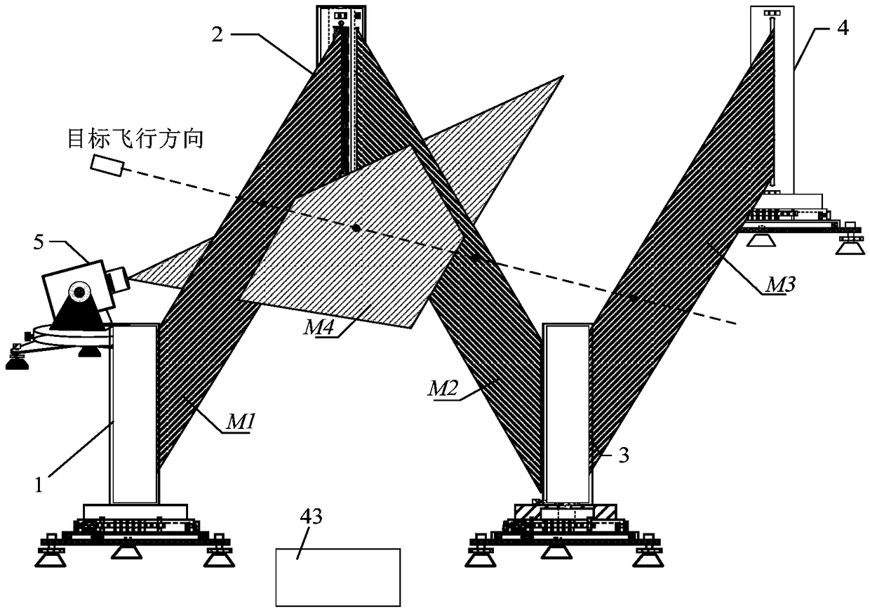
[0039] This embodiment relates to a discrete target position testing device, which is mainly used for testing multiple target positions, so as to obtain coordinate parameters of the multiple target positions.

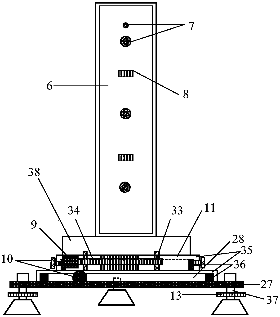
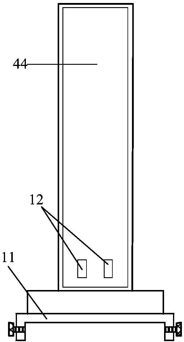
[0040] The discrete target position testing device involved in this embodiment is arranged at a certain distance along the extending direction of the flying target (generally referring to guns), and its arrangement is as follows: figure 1 As shown, it specifically includes a line laser emitting device 1 , a first line laser reflection device 2 , a second line laser reflection device 3 , a photoelectric detection receiving device 4 , a line array CCD device 5 and an intelligent signal acquisition instrument 43 . Wherein, the line laser emitting device 1 and the first line laser reflecting device 2 are coplanar as a group and placed perpendicular to the horizontal plane, and the line array CCD device 5 is arranged at the midpoint of the line between the line laser emitting...


PUM


Abstract

The invention provides a separate target position test device which comprises a line laser emitting device, a first line laser reflecting device, a second line laser reflecting device, a photoelectricdetection receiving device, a linear array CCD device and an intelligent signal collector, wherein the linear array CCD device is arranged at the center of a connecting line of the line laser emitting device and the first line laser reflecting device. Four detection light curtains are formed through the line laser emitting device, the first line laser reflecting device, the second line laser reflecting device, the photoelectric detection receiving device and the linear array CCD device. The test device provided by the invention overcomes the defects that a conventional integrated structure iscarried unfavorably, cannot move if being calibrated and cannot measure simultaneous landing of a plurality of targets, saves the cost, and is convenient to carry and flexible to calibrate. Meanwhile, the test device can measure the position coordinates of the targets which are landed simultaneously.

Description

technical field [0001] The invention relates to the technical field of photoelectric testing, in particular to a discrete target position testing device and testing method. Background technique [0002] In the field of weapon range testing, with the development of weapon development technology, the speed and position of high-speed continuous firing targets with high precision measurement and the matching and identification of multi-target parameters are one of the important assessment parameters for weapon calibration. At present, there are four-light-curtain intersection test system, six-light-curtain intersection test system, linear array CCD intersection test system, net target test system and acoustic target test system for the measurement of target parameters. The four-light curtain intersection test system mainly uses four sky-curtain targets or four light-curtain targets as the main body, which can obtain the speed and position parameters of a single target, and requi...

Claims


Application Information

Patent Timeline
IPC IPC(8): F41J5/02
CPCF41J5/02
Inventor 李翰山张晓倩苗旺
Owner XIAN TECHNOLOGICAL UNIV
Learn More