Optical imaging system and electronic device

An optical imaging system and image-side technology, applied in optics, optical components, instruments, etc., can solve the problems of increasing the height of the module, which is not conducive to the ultra-thinning of electronic devices, and achieves a short module height, which is conducive to miniaturization and reduces sensitivity. sexual effect

Inactive Publication Date: 2018-11-13
JIANGXI JINGCHAO OPTICAL CO LTD
View PDF0 Cites 6 Cited by
  • Summary
  • Abstract
  • Description
  • Claims
  • Application Information

AI Technical Summary

Problems solved by technology

The current conventional method is to increase the number of pixels by increasing the number of lenses, but the increase in the number of lenses will inevitably increase the height of the module, which is not conducive to the ultra-thinning of electronic devices

Method used


Image

  • Optical imaging system and electronic device
  • Optical imaging system and electronic device
  • Optical imaging system and electronic device

Examples


no. 1 approach

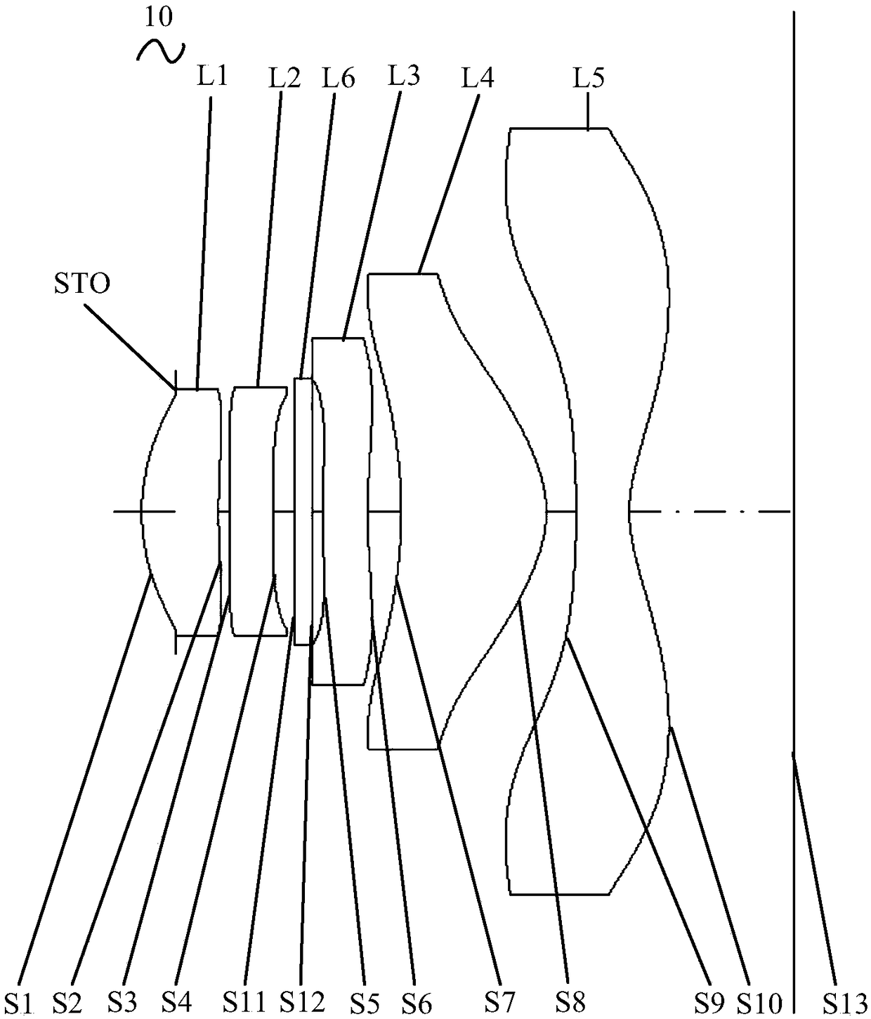
[0120] Please also refer to figure 1 , Figure 5 to Figure 7 , in the first embodiment, the first lens L1 has a positive refractive power, the second lens L2 has a negative refractive power, the third lens L3 has a negative refractive power, the fourth lens L4 has a positive refractive power, and the fifth lens L5 has a negative refractive power. Inflection force.

[0121] The object side S1 is convex; the image side S2 is concave on the optical axis and convex on the circumference; the object side S3 is concave on the optical axis and convex on the circumference; the image side S4 is concave; the object side S5 is on the optical axis It is convex at the center and concave at the circumference; the image side S6 is concave at the optical axis and convex at the circumference; the object side S7 is concave; the image side S8 is convex; the object side S9 is concave at the optical axis and at the circumference It is convex at the optical axis; the image side S10 is concave at t...

no. 2 approach

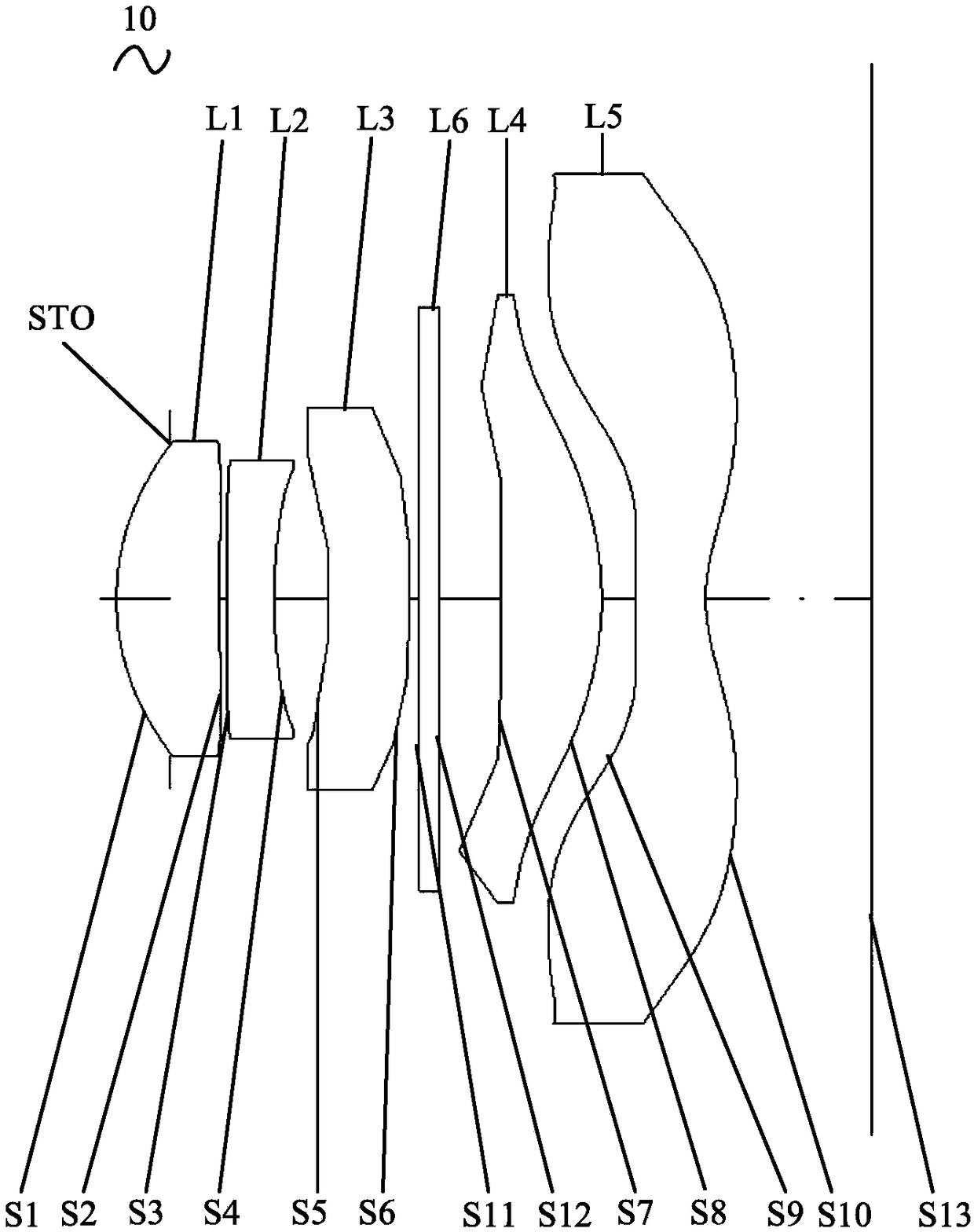
[0129] Please also refer to figure 2 , Figure 8 to Figure 10 , in the second embodiment, the first lens L1 has a positive refractive power, the second lens L2 has a negative refractive power, the third lens L3 has a positive refractive power, the fourth lens L4 has a positive refractive power, and the fifth lens L5 has a negative refractive power. Inflection force.

[0130] The object side S1 is convex; the image side S2 is concave at the optical axis and flat at the circumference; the object side S3 is convex; the image side S4 is concave; the object side S5 is concave; the image side S6 is convex; the object side S7 is Concave; image side S8 is convex; object side S9 is convex; image side S10 is concave.

[0131] The optical imaging system 10 satisfies the conditions of the following table:

[0132] table 3

[0133]

[0134]

[0135] Table 4

[0136]

[0137]

no. 3 approach

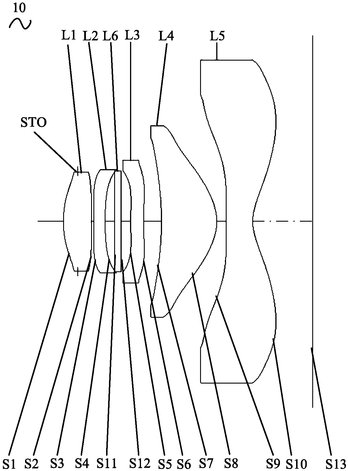
[0139] Please also refer to image 3 , Figure 11 to Figure 13 , in the third embodiment, the first lens L1 has a positive refractive power, the second lens L2 has a negative refractive power, the third lens L3 has a negative refractive power, the fourth lens L4 has a positive refractive power, and the fifth lens L5 has a negative refractive power. Inflection force.

[0140] The object side S1 is convex; the image side S2 is concave on the optical axis and convex on the circumference; the object side S3 is concave on the optical axis and convex on the circumference; the image side S4 is concave; the object side S5 is on the optical axis It is convex at the center and concave at the circumference; the image side S6 is concave at the optical axis and convex at the circumference; the object side S7 is concave; the image side S8 is convex; the object side S9 is convex; the image side S10 is at the optical axis Concave at the circumference and convex at the circumference.

[014...


PUM


Abstract

The invention discloses an optical imaging system and an electronic device. The optical imaging system includes a first lens with positive refractive power, a second lens with negative refractive power, a third lens with refractive power, a fourth lens with positive refractive power, and a fifth lens with negative refractive power, in order from the object side to the image side, wherein the object side surface of the first lens is a convex surface; the image side surface of the second lens is a concave surface at the circumference; the object side surface of the third lens is a concave surface at the circumference, and the image side surface of the third lens is a convex surface at the circumference; the object side surface of the fourth lens is a convex surface; and at least one of the object side surface and the image side surface of the fifth lens includes at least one inflexion point. The optical imaging system also includes an infrared optical filter which is arranged between theobject side surface of the first lens and the image side surface of the fifth lens. Through adjusting of the position of the infrared optical filter and reasonable matching of the five lenses, the optical imaging system can satisfy the high pixel demand and can realize ultra-thinning at the same time.

Description

technical field [0001] The invention relates to optical imaging technology, in particular to an optical imaging system and an electronic device. Background technique [0002] Electronic devices such as smart phones and tablets are generally equipped with an optical imaging system to realize the camera function. With the development of science and technology, people have higher and higher requirements for taking pictures, and optical imaging systems with high pixels are more favored by people. The current conventional method is to increase the number of pixels by increasing the number of lenses, but the increase in the number of lenses will inevitably increase the height of the module, which is not conducive to the ultra-thinning of electronic devices. Contents of the invention [0003] Embodiments of the present invention provide an optical imaging system and an electronic device. [0004] The optical imaging system according to the embodiment of the present invention in...

Claims


Application Information

Patent Timeline
Patent Type & Authority Applications(China)
IPC IPC(8): G02B13/00G02B13/18
CPCG02B13/0045G02B13/0055G02B13/18
Inventor 邹海荣兰宾利其他发明人请求不公开姓名
Owner JIANGXI JINGCHAO OPTICAL CO LTD
Why Eureka
Try Eureka