Humidity sensor based on substrate integrated waveguide reentrant resonant cavity

A substrate-integrated waveguide and humidity sensor technology, applied in the field of sensors, can solve the problems of large size of microwave passive sensors, reduction of relative volume of resonant cavity, and low quality factor, so as to ensure high quality factor, improve sensing sensitivity, and broad The effect of application range

Active Publication Date: 2019-10-18
SOUTHWEST UNIVERSITY
View PDF6 Cites 11 Cited by
  • Summary
  • Abstract
  • Description
  • Claims
  • Application Information

AI Technical Summary

Problems solved by technology

[0004] The present invention proposes a humidity sensor based on a substrate-integrated waveguide re-entrant resonant cavity. The purpose is to apply the folding technology to the substrate-integrated waveguide re-entrant re

Method used


Image

  • Humidity sensor based on substrate integrated waveguide reentrant resonant cavity
  • Humidity sensor based on substrate integrated waveguide reentrant resonant cavity
  • Humidity sensor based on substrate integrated waveguide reentrant resonant cavity

Examples


Embodiment Construction

[0032] In order to better illustrate the design process and purpose, the present invention will be further described below in conjunction with the embodiments and the accompanying drawings:

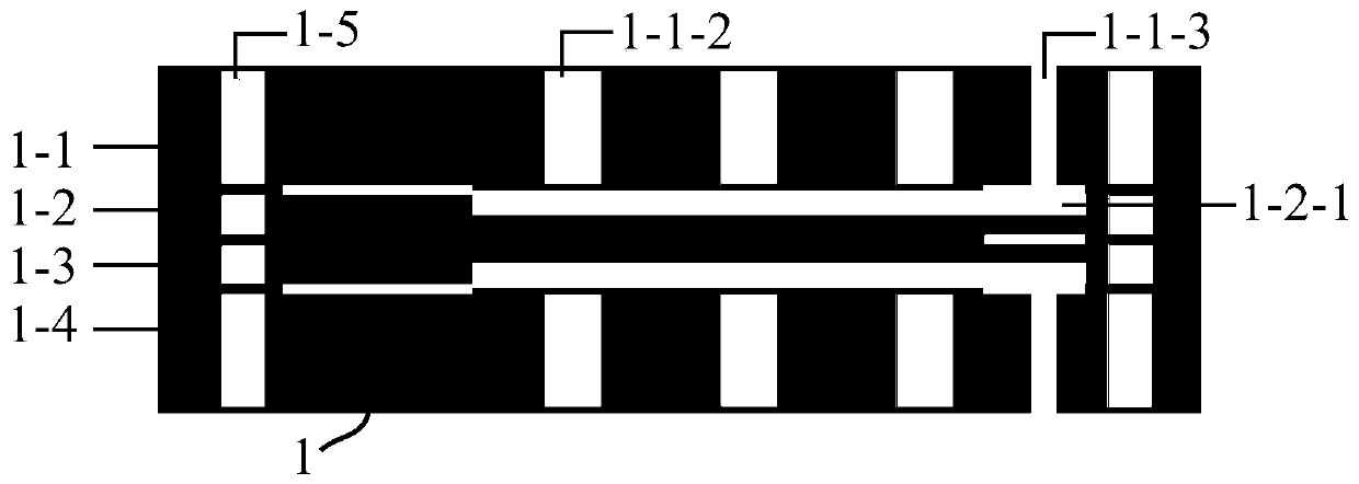
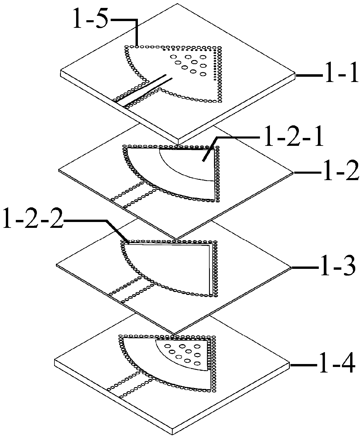
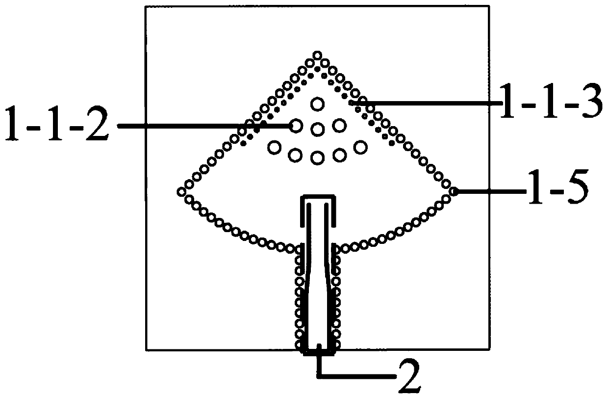
[0033] like Figure 1 to Figure 6(a) As shown in Fig. 6(b), the sensor based on the substrate integrated waveguide re-entrant re-entrant cavity proposed by the present invention comprises a substrate integrated waveguide re-entrant re-entrant re-entrant resonant cavity (1) and a section of coplanar waveguide feed with a characteristic impedance of 50Ω. Wire (2).

[0034] The resonant cavity (1) comprises a first dielectric substrate (1-1), a second dielectric substrate (1-2), a third dielectric substrate (1-3) and a fourth dielectric substrate (1-4), four The substrates are stacked vertically, and a resonant cavity cavity is formed in the middle, and the shape of the resonant cavity cavity is a quarter circle. The first dielectric substrate (1-1), the second dielectric substrate (1-2), ...


PUM

PropertyMeasurementUnit
Lengthaaaaaaaaaa
Outside widthaaaaaaaaaa
Inner widthaaaaaaaaaa

Abstract

A humidity sensor based on a substrate integrated waveguide reentrant resonant cavity comprises a substrate integrated waveguide reentrant resonant cavity and a coplanar waveguide feeder line. The reentrant resonant cavity is formed by vertically stacking four dielectric substrates, and an intermediate dielectric layer of each dielectric substrate is etched with a plurality of metallized through holes that are uniformly distributed outside the resonant cavity and on both sides of the feeder line. The intermediate dielectric layers of the second dielectric substrate and the third dielectric substrate are both etched with fan-shaped grooves, and the bottom metal layer of the second dielectric substrate and the top metal layer of the third dielectric substrate are etched with L-shaped strip grooves. In the invention, a stacking technique is applied in the substrate integrated waveguide reentrant resonant cavity, so as to ensure high quality factor of the resonant cavity and greatly reducerelative size of the resonant cavity, and introduce a sensing region at the strong induced electric field of the resonant cavity to excite strong interaction between the induced electric field and wet air media in the resonant cavity. The humidity sensor of the invention is compact in structure and easy to process and integrate.

Description

technical field [0001] The invention belongs to the field of sensors, in particular to a microwave passive sensor suitable for detecting air relative humidity. Background technique [0002] Humidity is an important indicator in environmental quality monitoring. Monitoring and controlling humidity is very important in many application scenarios. For example, the relative humidity of the air in a greenhouse will directly affect the growth and health of crops. When storing food, it is necessary to control the relative humidity of the environment at an appropriate level to delay the spoilage of the food. Other fields, such as material handling, machinery manufacturing, and large-scale equipment operation, all have higher requirements on ambient humidity. Therefore, the development of high-performance humidity sensors has high practical value in many fields. [0003] Traditional humidity sensors such as resistive sensors, capacitive sensors and piezoelectric sensors all work at...

Claims


Application Information

Patent Timeline
IPC IPC(8): G01N27/00
CPCG01N27/00
Inventor 黄杰魏治华李俊杉倪星生刘旭扬
Owner SOUTHWEST UNIVERSITY
Why Eureka
Try Eureka