Rotary multi-surface advertising board
A billboard and installation surface technology, applied in the field of billboards, can solve problems such as unfavorable energy saving and environmental protection, lower energy utilization rate, small visual impact, etc., achieve good display effect and increase display space
- Summary
- Abstract
- Description
- Claims
- Application Information
AI Technical Summary
Problems solved by technology
Method used
Image

Examples
Embodiment 1
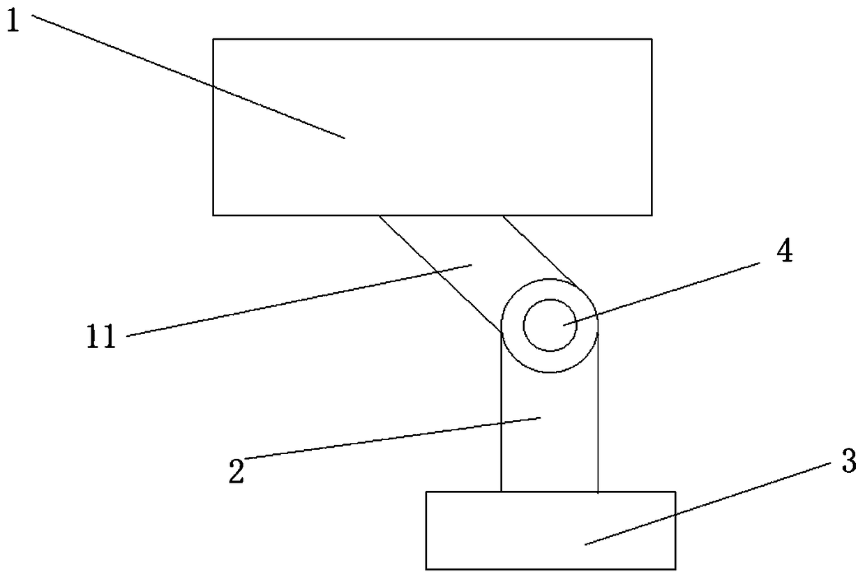
[0049] A rotating multi-faceted billboard, combined with figure 1 As shown, it includes a multi-sided billboard 1, a central support rod 2, a support platform 3, a driving mechanism 4, and a connecting shaft 11;
[0050] The supporting table 3 is located at the bottom of the rotating multi-faceted billboard, which is used to form the base and support the upper structure. The central supporting rod 2 is installed on the supporting table 3. The driving mechanism 4 is arranged on the central supporting rod 2. The connecting shaft 11 connects the driving mechanism 4 and the multi-faceted billboard. The billboard 1, the driving mechanism 4 can drive the connecting shaft 11 to move up and down while rotating around the shaft, so as to drive the multi-faceted billboard 1 to rotate in multiple directions;
[0051] Drive mechanism 4 comprises drive motor and receiving shaft, and receiving shaft connects connecting shaft 11 and central support rod 2, and driving motor is used for drivin...
Embodiment 2
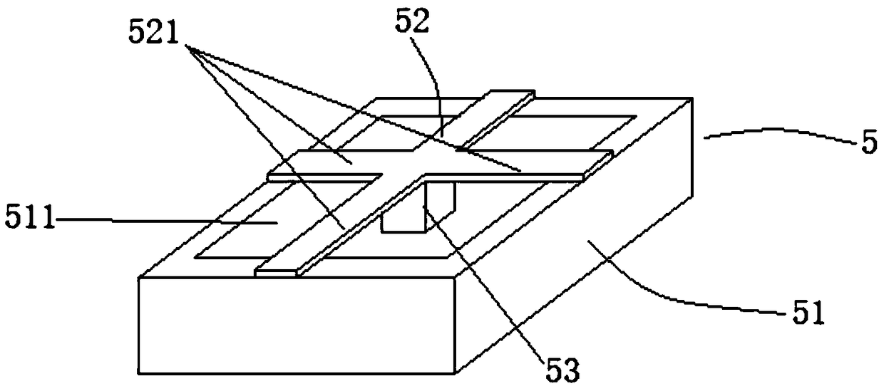
[0056] As the above-mentioned rotating multi-faceted billboard, the difference of this embodiment is that the combination figure 1 and figure 2 As shown, the driving mechanism 4 is provided with at least one energy harvester 5, which is used to collect the mechanical energy generated when the multi-faceted billboard 11 moves up and down. The energy harvester 5 includes an outer frame 51 and an electrical conversion assembly 52. The connecting assembly is used to install the energy harvester 5 on the driving mechanism 4. The electric conversion assembly 52 includes at least one cantilever beam 521, and the surface of the cantilever beam 521 is attached with a piezoelectric material. The piezoelectric material vibrates back and forth Charges can be generated under certain circumstances. The cantilever beam 521 is located at the first installation surface 511 of the outer frame 51 and is fixed on the frame edge of the outer frame 51. The first installation surface 511 is a thro...
Embodiment 3
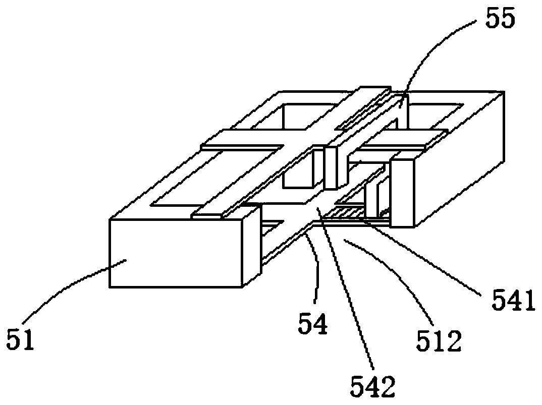
[0067] As the above-mentioned rotating multi-faceted billboard, the difference of this embodiment is that the combination Figure 3 to Figure 8 As shown, the energy harvester also includes a frequency modulation structure 54 and at least one self-feedback structure 55 for adjusting the vibration frequency of the electrical conversion component 52; the frequency modulation structure 54 is located at the second mounting surface 512 of the outer frame 51 and is fixedly installed on the outer frame 51 On the edge of the frame, the second installation surface 512 and the first installation surface 511 are respectively located on opposite sides of the side wall of the outer frame 51, and the second installation surface 512 is a through structure, which penetrates with the area formed by the side wall of the outer frame 51. , to facilitate the frequency modulation structure 54 to generate resonance;
[0068] The frequency modulation structure 54 includes at least one frequency modul...
PUM
 Abstract
Description
Claims
Application Information
 - Generate Ideas
- Intellectual Property
- Life Sciences
- Materials
- Tech Scout
- Unparalleled Data Quality
- Higher Quality Content
- 60% Fewer Hallucinations
Browse by: Latest US Patents, China's latest patents, Technical Efficacy Thesaurus, Application Domain, Technology Topic, Popular Technical Reports.
© 2025 PatSnap. All rights reserved.Legal|Privacy policy|Modern Slavery Act Transparency Statement|Sitemap|About US| Contact US: help@patsnap.com