Microfluidic substrate, driving method thereof and miniaturized total analysis system

A microfluidic and substrate technology, applied in the field of micro-total analysis systems, can solve the problems of large size occupied area and limitation of switching transistors, and achieve the effect of high resolution and resolution

Active Publication Date: 2018-11-16
BOE TECH GRP CO LTD
View PDF5 Cites 16 Cited by
  • Summary
  • Abstract
  • Description
  • Claims
  • Application Information

AI Technical Summary

Problems solved by technology

[0005] The inventors have found that there are at least the following problems in the prior art: in the existing micro-total analysis system, the driving electrodes for driving the liquid droplets to move, and the photosensitive sensors for judging the information such as the position and composition of the liquid droplets need to be connected with their corresponding switch units ( Usually it is

Method used


Image

  • Microfluidic substrate, driving method thereof and miniaturized total analysis system
  • Microfluidic substrate, driving method thereof and miniaturized total analysis system
  • Microfluidic substrate, driving method thereof and miniaturized total analysis system

Examples


Embodiment 1

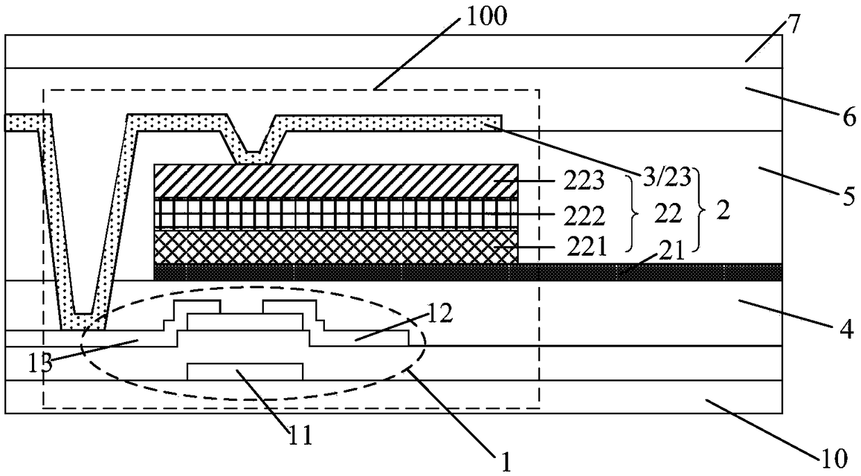
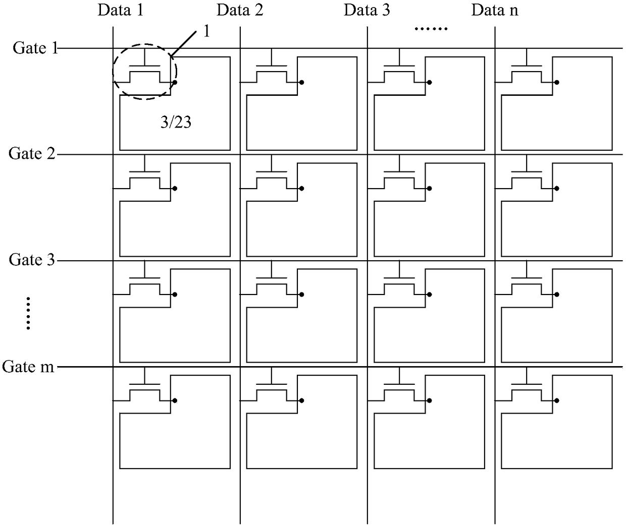
[0051] This embodiment provides a microfluidic substrate, including: a base, a plurality of detection modules located on the base; each detection module includes: a switch unit, a drive electrode, and a photosensitive unit located on the base; wherein, the drive electrodes are connected to the switch unit The signal output end of the photosensitive unit, and one of the first pole and the second pole of the photosensitive unit is also connected to the signal output end of the switch unit.

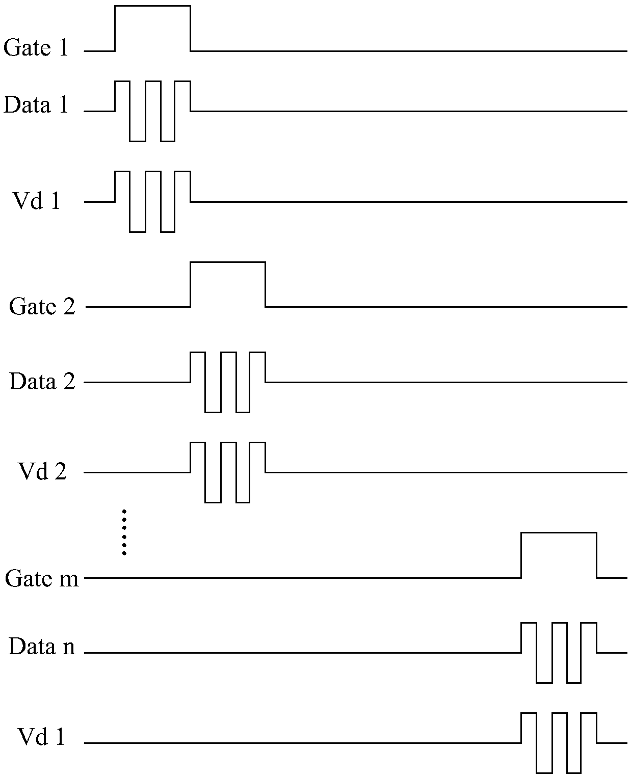
[0052]Since in the microfluidic substrate of this embodiment, the driving electrodes and photosensitive units in each detection module are connected to the same switch unit, therefore, applying the microfluidic substrate to the micro-total analysis system can be performed in the droplet driving stage. , control the switch unit to open, and input the first voltage to the signal receiving end of the switch unit, and transmit it to the driving electrode, then control the switch unit to close, an...

Embodiment 2

[0069] combine Figure 5 As shown, this embodiment provides a micro-total analysis system, which includes the microfluidic substrate in Example 1. Therefore, the micro-total analysis system in this embodiment can achieve high-resolution design.

[0070] Of course, the micro-total analysis system in this embodiment also includes an optical unit 8 configured to form light irradiated to the driving electrodes 3 . Wherein, the optical unit 8 includes: a light source 81 and an optical waveguide layer 82; specifically, the light source 81 is arranged on the side of the optical waveguide layer 92, and can output multiple paths of light with different wavelengths; the optical waveguide layer 82 and the microfluidic The control board is relatively set.

[0071] Wherein, during droplet driving and droplet detection, the droplet is located between the microfluidic substrate and the optical unit 8, as Figure 5 shown. Specifically, the movement of the driven droplet is realized by cont...


PUM


Abstract

The invention provides a microfluidic substrate, a driving method thereof and a miniaturized total analysis system. The microfluidic substrate provided by the invention comprises a substrate and a plurality of detection modules located on the substrate, wherein each detection module comprises a switching unit located on the substrate and a driving electrode connected with a signal output terminalof the corresponding switching unit; each detection module further comprises a light sensitizing unit located on the substrate; and either first poles or second poles of the light sensitizing units are connected with signal output terminals of the switching units. According to the microfluidic substrate provided by the invention, the corresponding driving electrode and the corresponding sensitizing unit of each detection module share one switching unit, so that compared with the prior art, more detection modules can be arranged on the microfluidic substrate of a unit area, and thus, the realization of the high-resolution microfluidic substrate is facilitated.

Description

technical field [0001] The invention relates to a microfluidic substrate, a driving method thereof, and a micro total analysis system. Background technique [0002] Micro-Total Analysis System (micro-Total Analysis System, Micro-Total Analysis System) [0003] The purpose is to maximize the transfer of the functions of the analysis laboratory to portable analysis equipment through the miniaturization and integration of chemical analysis equipment, and even integrate it into a chip with a small size. The ultimate goal is to realize the "personalization" and "home use" of analytical laboratories, so that analytical science and analytical instruments can be liberated from chemical laboratories and enter thousands of households. [0004] In the micro-total analysis system, it is possible to control the behavior of micro-droplet movement, separation, aggregation, chemical reaction, and biological detection. The droplet is moved to the specified position through the driving elec...

Claims


Application Information

Patent Timeline
IPC IPC(8): B01L3/00G01N15/10
CPCG01N15/10G01N15/1056B01L3/50273B01L2400/0415B01L2300/0809B01L2300/0627G01N2015/1087G01N2015/105B01L3/00G01N2015/0693B01L3/502792B01L2300/0645B01L2300/0663B01L2300/12B01L2300/165G01N15/1484H01L27/1446
Inventor 刘英明王海生董学丁小梁车春城蔡佩芝顾品超李昌峰王雷
Owner BOE TECH GRP CO LTD
Why Eureka
Try Eureka