Eureka AIR delivers breakthrough ideas for toughest innovation challenges, trusted by R&D personnel around the world.

Bonding jig and method for manufacturing display device

A technology for fitting a jig and a manufacturing method, which is applied in the direction of manufacturing tools, hand-held tools, instruments, etc., can solve problems such as low success rate, and achieve the effects of low production cost, high yield rate and simple operation process

Active Publication Date: 2020-09-04
WUHAN CHINA STAR OPTOELECTRONICS SEMICON DISPLAY TECH CO LTD
View PDF6 Cites 0 Cited by
  • Summary
  • Abstract
  • Description
  • Claims
  • Application Information

AI Technical Summary

Problems solved by technology

[0004] The technical problem to be solved by the present invention is to provide a bonding fixture and a manufacturing method of a display device to solve the low success rate of complete bonding of a curved cover plate and a curved display module in the prior art The problem

Method used


Image

  • Bonding jig and method for manufacturing display device
  • Bonding jig and method for manufacturing display device
  • Bonding jig and method for manufacturing display device

Examples


Embodiment Construction

[0035] The following will clearly and completely describe the technical solutions in the embodiments of the present invention with reference to the accompanying drawings in the embodiments of the present invention. Obviously, the described embodiments are only some of the embodiments of the present invention, not all of them. Based on the embodiments of the present invention, all other embodiments obtained by persons of ordinary skill in the art without making creative efforts belong to the protection scope of the present invention.

[0036] In the description of the embodiments of the present application, it should be understood that the orientation or positional relationship indicated by the term "thickness" is based on the orientation or positional relationship shown in the drawings, and is only for the convenience of describing the application and simplifying the description, rather than implying Or an indication that the device or element referred to must have a particular...


PUM


Abstract

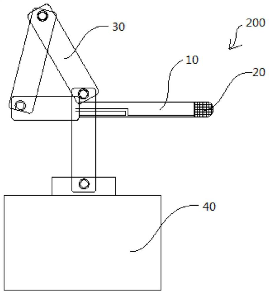
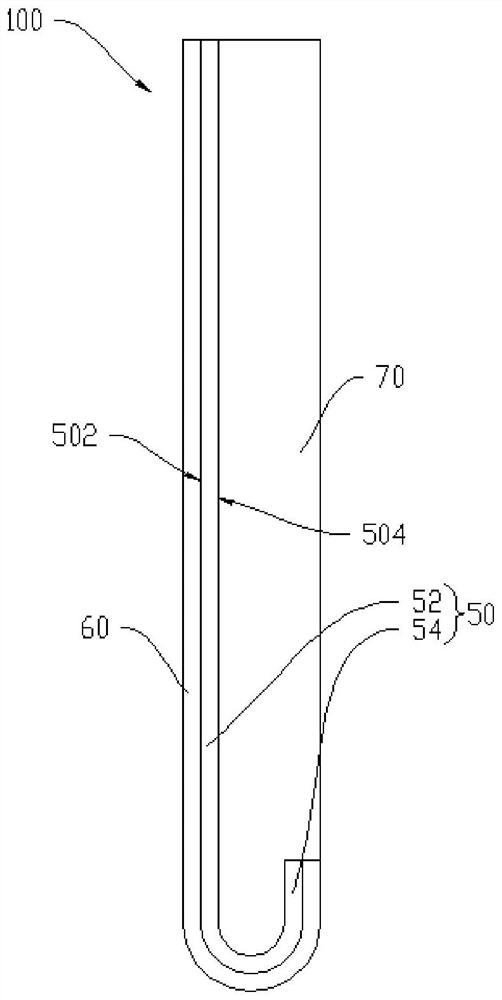
The invention discloses a bonding tool for bonding a flexible display module with a cover plate. The bonding tool comprises a rigid piece, an air bag positioned on one side of the thickness directionof the rigid piece and connected with the rigid piece to form a main body piece, and an elastic piece fixed at one end of the length direction of the main body piece, wherein the surface of the airbagand the surface of the elastic piece are used for bonding with the flexible display module. The invention further discloses a manufacturing method of display equipment. When the flexible display module in such bent shapes as U form is bonded with the cover plate, the flexible display module is bonded on the bonding tool; then, the flexible display module butts against the cover plate through theelastic piece; the elastic piece is deformed to bond the bent section of the flexible display module with the bent part of the cover plate; and the airbag is inflated; the airbag expands to eject a plane section of the flexible display module, so that the plane section of the flexible display module is bonded with a plane part of the cover plate, the yield is high, and the production cost is low.

Description

technical field [0001] The invention relates to the field of display technology, in particular to a bonding fixture and a manufacturing method of a display device. Background technique [0002] With the development of science and technology, flexible display devices show more and more extensive application prospects. The foldability of flexible display devices can realize product diversification and achieve excellent display effects and appearance effects. A flexible display device is generally realized by using an organic light-emitting diode (Organic Light-Emitting Diode, OLED) display screen. [0003] In order to achieve a larger display range and a novel display effect, the display module can be designed in a bent shape, such as a U shape, and a cover plate with the same shape as the display module can be pasted on the display surface of the display module to protect Display mods. In the prior art, the success rate of complete bonding between the curved cover plate an...

Claims


Application Information

Patent Timeline
Patent Type & Authority Patents(China)
IPC IPC(8): B25B27/00G09F9/30
CPCB25B27/00G09F9/301
Inventor 王明亮
Owner WUHAN CHINA STAR OPTOELECTRONICS SEMICON DISPLAY TECH CO LTD
Why Eureka
Eureka Blog
Learn More