
Semiconductor light-emitting element and process for production thereof

a technology of semiconductors and light-emitting elements, which is applied in the direction of semiconductor/solid-state device manufacturing, semiconductor devices, electrical devices, etc., can solve the problems of small light-emitting area, device can work stably, and shaded light emitted from the active layer, so as to achieve not particularly restricted opening shapes

Inactive Publication Date: 2012-01-24
KK TOSHIBA
View PDF11 Cites 28 Cited by
  • Summary
  • Abstract
  • Description
  • Claims
  • Application Information

AI Technical Summary

Benefits of technology

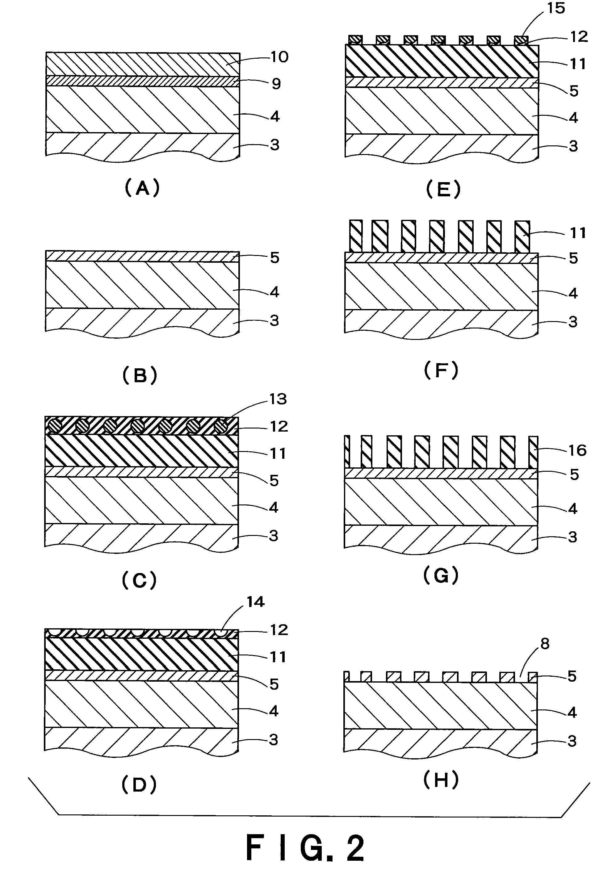
The present invention provides a semiconductor light-emitting element with a metal electrode layer that has high light-transparency and is in good ohmic contact with the neighboring layer to have low contact resistance. This results in high external quantum efficiency, allowing for brighter and more intense emission than previous elements. The semiconductor light-emitting element has a crystal substrate, an electrode layer, a semiconductor layer, and a metal electrode layer with continuous metal parts and openings. The process for producing the semiconductor light-emitting element involves forming a metal electrode layer on the semiconductor layer and using a mask pattern to transfer the openings to the metal electrode layer.

Problems solved by technology

Further, because of low contact resistance, the resultant device can work stably.
However, in the case where a metal electrode is adopted, a light-emitting area is small because the electric current flows only just under the electrode or near there.
Further, it is also a problem that light emitted from the active layer is shaded by the opaque metal electrode.
As a result, the light-extraction efficiency of the semiconductor light-emitting element is too lowered to give off a sufficient amount of emission.
However, they are yet to succeed in obtaining sufficient intensity of emission given off from the whole surface.
Further, it is also a problem that the transparent conductive oxide layer shows poorly adhesion to the metal electrode.

Method used


Image

  • Semiconductor light-emitting element and process for production thereof
  • Semiconductor light-emitting element and process for production thereof
  • Semiconductor light-emitting element and process for production thereof

Examples


example 1

[0071]Firstly, a semiconductor light-emitting element comprising an active layer of InGaAIP in DH structure was produced.

[0072]The (100) face of n-type Si-doped GaAs was used as a crystal substrate. On the substrate, an n-type semiconductor layer (thickness: 1 μm) made of n-In0.5(Ga0.3Al0.7)0.5P doped with Si was formed by the MOCVD method from trimethylindium (hereinafter, referred to as “TMI”), trimethylgallium (hereinafter, referred to as “TMG”), trimethylaluminum (hereinafter, referred to as “TMA”), PH3 and SiH4. Successively, an active layer of In0.5(Ga0.8Al0.2)0.5P having 0.6 μm thickness was formed thereon from TMI, TMG, TMA and PH3, and then a p-type semiconductor layer (thickness: 1 μm) of p-In0.5(Ga0.3Al0.7)0.5P doped with Zn was produced from TMI, TMG, TMA, PH3 and dimethylzinc (hereinafter, referred to as “DMZ”). Further, a current-spreading layer (thickness: 5 ρm) of p-GaP doped with Zn was formed from TMG, PH3 and DMZ.

[0073]Thereafter, on the whole bottom surface of th...

example 2

[0087]Secondly, a semiconductor light-emitting element comprising an active layer of InGaAIP in DH structure and an n-type semiconductor layer on the light-extraction side was produced.

[0088]On a p-GaAs substrate, a p-type semiconductor layer (thickness: 1 μm) of p-In0.5(Ga0.3Al0.7)0.5P doped with Zn was formed by the MOCVD method. Successively, an active layer of In0.5(Ga0.8Al0.2)0.5P having 0.6 μm thickness was formed, and then an n-type semiconductor layer (thickness: 1 μm) of n-In0.5(Ga0.3Al0.7)0.5P doped with Si was formed thereon. Further, a current-spreading layer (thickness: 5 μm) of n-GaP doped was formed thereon.

[0089]Thereafter, on the whole bottom surface of the p-GaAs substrate, an Au thin film (thickness: 50 nm) was vapor-deposited and then an AuZn-alloy thin film (thickness: 200 nm) was deposited thereon to form a p-type electrode layer. On the other hand, on the current-spreading layer, another Au thin film (thickness: 50 nm) and an AuGe-alloy thin film (thickness: 2...

example 3

[0092]Thirdly, the procedures of Example 1 were repeated except that the ohmic contacts were formed after the openings were formed on the p-type electrode layer, to produce a semiconductor light-emitting element. The obtained element gave off as intense emission as that of Example 1 did. Further, in the produced element, the Zn-diffusion layer, which was formed by the ohmic contact between the p-type electrode layer and the p-type semiconductor layer, was continuously present only in the lower part of the p-type electrode layer.


PUM

PropertyMeasurementUnit
thicknessaaaaaaaaaa
opening diameteraaaaaaaaaa
diameteraaaaaaaaaa

Abstract

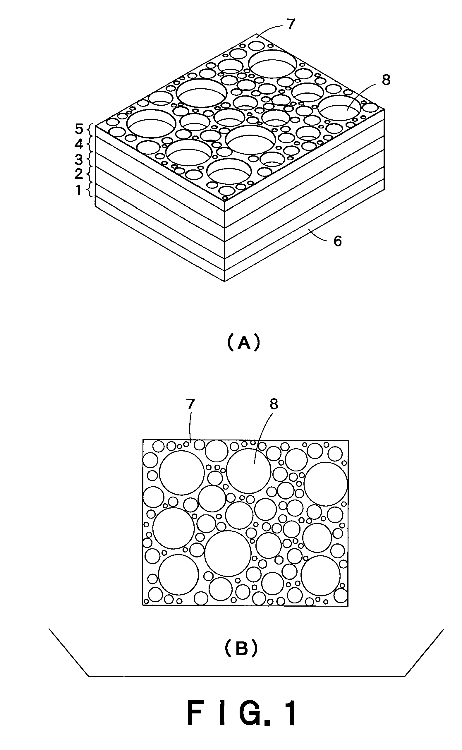
The present invention provides a semiconductor light-emitting element comprising an electrode part excellent in ohmic contact and capable of emitting light from the whole surface. An electrode layer placed on the light-extraction side comprises a metal part and plural openings. The metal part is so continuous that any pair of point-positions in the part is continuously connected without breaks, and the metal part in 95% or more of the whole area continues linearly without breaks by the openings in a straight distance of not more than ⅓ of the wavelength of light emitted from an active layer. The average opening diameter is of 10 nm to ⅓ of the wavelength of emitted light. The electrode layer has a thickness of 10 nm to 200 nm, and is in good ohmic contact with a semiconductor layer.

Description

CROSS-REFERENCE TO RELATED APPLICATIONS[0001]This application is based upon and claims the benefit of priority from the prior Japanese Patent Applications No. 77421 / 2008, filed on Mar. 25, 2008; the entire contents of which are incorporated herein by reference.BACKGROUND OF THE INVENTION[0002]1. Field of the Invention[0003]The present invention relates to a semiconductor light-emitting element comprising a light-transmitting metal electrode provided with fine openings, and also relates to a process for production thereof.[0004]2. Background Art[0005]A metal electrode is generally employed as an electrode provided on a semiconductor layer in a semiconductor light-emitting element. If produced from metals by the alloying process, the electrode is brought into such good ohmic contact with the semiconductor layer that a great deal of electric current can be injected into an active layer. Further, because of low contact resistance, the resultant device can work stably.[0006]However, in t...

Claims


Application Information

Patent Timeline
Patent Type & Authority Patents(United States)
IPC IPC(8): H01L33/00H01L33/30H01L33/36H01L33/38H01L33/40
CPCH01L33/38H01L2933/0091
Inventor KITAGAWA, RYOTAASAKAWA, KOJIFUJIMOTO, AKIRANAKANISHI, TSUTOMUTSUTSUMI, EISHI
Owner KK TOSHIBA
Learn More