Noise-reduction structure of outside wall of building

A technology for buildings and exterior walls, which is applied to building structures, building components, and sound insulation. It can solve problems such as poor noise reduction effects on exterior walls, and achieve the effects of improving noise reduction effects and changing sound absorption effects

Active Publication Date: 2018-11-16
CHONGQING JIANZHU COLLEGE
View PDF10 Cites 3 Cited by
  • Summary
  • Abstract
  • Description
  • Claims
  • Application Information

AI Technical Summary

Problems solved by technology

[0003] The present invention intends to provide a noise reduction structure for building exterior walls to

Method used


Image

  • Noise-reduction structure of outside wall of building

Examples


Embodiment 1

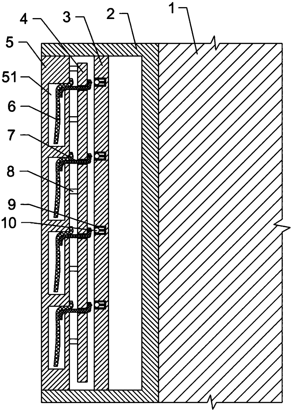
[0015] Embodiment 1: as attached figure 1 Shown: The noise reduction structure of the exterior wall of the building, including a sound-absorbing unit, the sound-absorbing unit includes a box 2 fixedly installed on the outside of the wall 1, and the side of the box 2 away from the wall 1 is provided with an opening; the opening is covered with a sound-absorbing Board 5, the sound-absorbing board 5 is sealed and matched with the box body 2 through rubber pads, and the sound-absorbing board 5 is connected with the box body 2 through bolts; the interior of the sound-absorbing board 5 is provided with several water storage chambers 51, and the water storage chambers 51 are in a rectangular array distributed. The right side of the sound-absorbing panel 5 is provided with a transverse water flow channel, and the water flow channel communicates with the upper part of the water storage cavity 51 . The first water-absorbent sliver 6 and the second water-absorbent sliver 7 are arranged ...

Embodiment 2

[0017] Embodiment 2: The only difference from Embodiment 1 is that the water retaining member is a water retaining plate, and the water retaining plate is hinged to the conduit 9 .

[0018] The specific implementation process is as follows: during the day, due to the high temperature, the thermal expansion block 8 absorbs the heat outside the wall body 1 and expands, so that the moving plate 4 is away from the sound-absorbing panel 5 under the action of the thermal expansion block 8 and close to the limit Plate 3, so that the moving plate 4 separates the water retaining member from the drain hole through the ejector rod, so that the water in the conduit 9 flows into between the moving plate 4 and the limiting plate 3, and through the capillary action of the second absorbent cotton sliver 7 and siphon effect from the upper end of the second absorbent cotton 7 to the lower end, and enter the water storage chamber 51, thereby replenishing the water storage chamber 51, increasing t...


PUM


Abstract

The invention relates to the technical field of building maintenance structures, in particular to a noise-reduction structure of an outside wall of a building. The noise-reduction structure comprisesa sound absorption unit, wherein the sound absorption unit comprises a box body fixedly arranged on the outside of a wall body. An opening is formed in the box body, and a sound absorption plate is covered on the opening. A plurality of water storage cavities are formed in the sound absorption plate and a water flow channel is arranged on the sound absorption plate. A moving plate is arranged at the side, face to the box body, of the sound absorption plate, wherein thermal expansion blocks are connected between the moving plate and the sound absorption plate, and first water absorption cottonslivers and second water absorption cotton slivers extending into the water storage cavities are arranged in the water flow channel. A limiting plate is parallelly arranged on the side, far from the sound absorption plate, of the moving plate, and the limiting plate is fixedly connected with the box body. The upper ends of the second water absorption cotton slivers horizontally pass through the moving plate and are arranged between the moving plate and the limiting plate. A plurality of horizontal conduits are arranged on the side wall, face to the moving plate, of the limiting plate in an embedded mode, and a plurality of drain holes are formed in the side, face to the moving plate, of the conduits. The noise-reduction structure of the outside wall of the building solves the problem thatthe noise-reduction effect of the outside wall of the building is poor in the prior art.

Description

technical field [0001] The invention relates to the technical field of building maintenance structures, in particular to a noise reduction structure for building exterior walls. Background technique [0002] The exterior wall of the building surrounds the interior of the building, thus playing the role of isolating the interior of the building from the exterior. In order to reduce the impact of external sound on the interior space of the building, the exterior wall needs to have a certain sound insulation and noise reduction function. The sound insulation and noise reduction structures of the exterior walls of existing buildings are generally relatively simple, and can only deal with sounds in a small frequency range, and do not make corresponding adjustments according to the different environments in which the buildings are located, resulting in The noise reduction effect of the external wall is relatively poor. For example, in the buildings around the vegetable market, b...

Claims


Application Information

Patent Timeline
IPC IPC(8): E04B1/84E04B1/86
CPCE04B1/84E04B1/86E04B2001/8476
Inventor 骆文进王丽英孟令峰
Owner CHONGQING JIANZHU COLLEGE
Why Eureka
Try Eureka