Supercharge Your Innovation With Domain-Expert AI Agents!

Locks, Bikes & Carts

A lock and lock pin technology, which is applied in the field of locks, can solve the problems of low service life of bicycles or vehicle piles, no emergency unlocking function, poor user experience, etc., and achieves the effect of simple structure, small space occupation, and good feeling of use.

Active Publication Date: 2020-11-20
ZHUHAI UNITECH POWER TECH CO LTD
View PDF14 Cites 0 Cited by
  • Summary
  • Abstract
  • Description
  • Claims
  • Application Information

AI Technical Summary

Problems solved by technology

[0004] The main purpose of the present invention is to provide a lock, a bicycle and a bicycle to solve the problem that the bicycle or bicycle lock in the prior art does not have an emergency unlocking function, resulting in a low service life and a poor user experience of the bicycle or bicycle. question

Method used


Image

  • Locks, Bikes & Carts
  • Locks, Bikes & Carts
  • Locks, Bikes & Carts

Examples


Embodiment 1

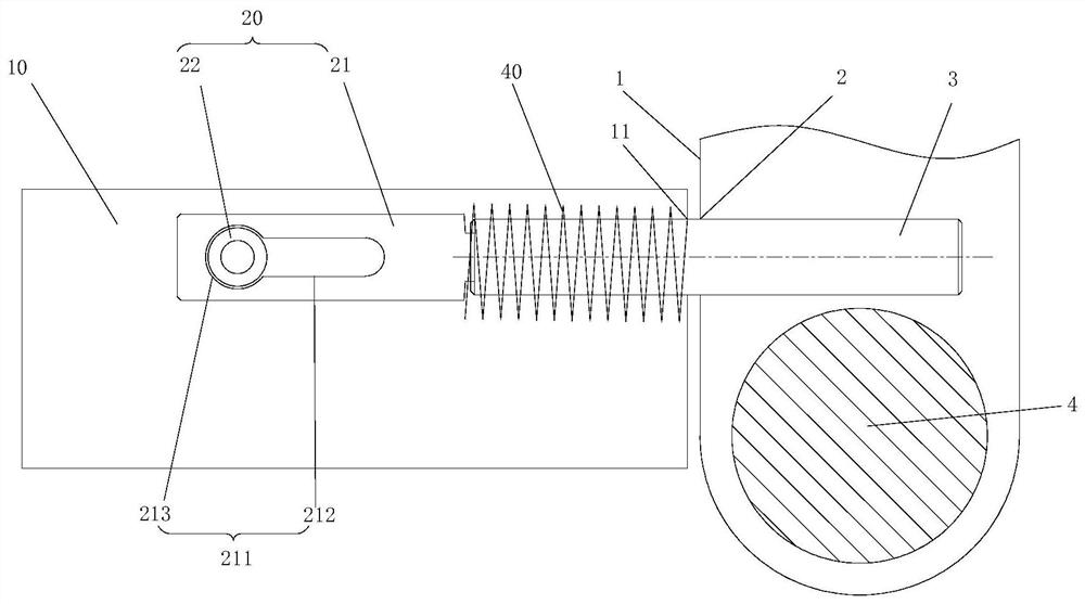
[0043] like Figure 1 to Figure 4 As shown, the limit assembly 20 includes a linkage 21 and a bayonet 22. The interlock 21 is movably arranged in the mounting shell 10 and connected with the locking pin 3. The interlocking member 21 is provided with a sliding hole 211, and the bayonet 22 is provided with a sliding hole 211. In the installation shell 10, it can be telescopically penetrated at the sliding hole 211. When the locking pin 22 fully extends into the sliding hole 211, the linkage 21 is locked, and the limiting component 20 is in the limiting state. When at least a part of 22 exits the sliding hole 211 , the linkage 21 moves in a direction away from the locking hole 2 , and the limiting assembly 20 is in an avoidance state. Through the cooperating use of the bayonet 22 and the linkage member 21, the limit assembly 20 is switched between the limit state and the avoidance state; specifically, when the lock is in the normal use state, the bayonet 22 completely extends int...

Embodiment 2

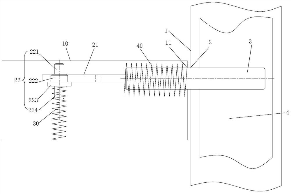
[0049] like Figure 5 to Figure 10 As shown, the limit assembly 20 includes a connecting plate 23 and a stop sleeve 24 , the connecting plate 23 is rotatably arranged in the mounting shell 10 and connected with the locking pin 3 , and the stopping sleeve 24 is arranged on the connecting plate 23 away from the lock On one side of the pin 3, the first surface of the stopper sleeve 24 opposite to the connecting plate 23 is provided with an escape hole 241, and the projected shape of the connecting plate 23 on the first surface of the stopper sleeve 24 can fall into the escape hole 241. Through the cooperation of the connecting plate 23 and the stop sleeve 24, the limit assembly 20 is switched between the limit state and the avoidance state; The avoidance holes 241 are staggered, and the connecting plate 23 is in contact with the first surface of the stop sleeve 24. At this time, the lock pin 3 protrudes from the mounting hole 11 of the mounting shell 10 by a set distance. The p...


PUM


Abstract

The invention provides a lock, a bicycle and a vehicle pile, the lock comprises a main lock body and a lock pin, a lock hole is formed in the main lock body, the lock pin extends into or exits from the lock hole in the axial direction of the lock pin, and has a locking position and an unlocking position in the movement direction, the lock pin moves back and forth between the locking position and the unlocking position so as to realize locking and unlocking of the lock, the lock further comprises an emergency unlocking component, the emergency unlocking component is used for realizing emergencyunlocking of the lock under an emergency condition, the emergency unlocking assembly comprises a mounting shell and a limiting assembly, the limiting assembly is arranged in the mounting shell and isconnected with the locking pin, the limiting assembly is provided with a limiting state for limiting the locking pin in the locking position and an avoiding state enabling the locking pin to retractinto the mounting shell to exit the locking hole. The invention solves the problem that the lock of the bicycle or the vehicle pile in the prior art has no emergency unlocking function, so that the problems that the service life of the bicycle or the bicycle pile is low and the use experience is poor are solved.

Description

technical field [0001] The present invention relates to the technical field of locks, in particular, to a lock, a bicycle and a vehicle pole. Background technique [0002] The lock of the bicycle in the prior art does not have an emergency unlocking function. After the lock is damaged, the bicycle can only be transported to the repair site and the lock is violently removed, which is not only time-consuming and labor-intensive, but also causes damage to the bicycle body, thereby affecting the bicycle. service life, and lead to a poor use experience of the bicycle. [0003] The lock of the car pile in the prior art does not have an emergency unlocking function. When the car pile is in a damaged state or a powerless state, the lock of the car pile can only be removed violently, which is not only time-consuming and laborious, but also causes damage to the car pile body. As a result, the service life of the vehicle pile is affected, and the use experience of the vehicle pile is ...

Claims


Application Information

Patent Timeline
Patent Type & Authority Patents(China)
IPC IPC(8): E05B15/00E05B71/00
CPCE05B15/00E05B71/00
Inventor 温联森杨绍华李启平
Owner ZHUHAI UNITECH POWER TECH CO LTD
Features
  • R&D
  • Intellectual Property
  • Life Sciences
  • Materials
  • Tech Scout
  • Unparalleled Data Quality
  • Higher Quality Content
  • 60% Fewer Hallucinations
Learn More