Method of dynamic and variable parameter well-killing technology

A process method and variable parameter technology, applied in drilling equipment and methods, drilling equipment, earthwork drilling, etc., can solve the problems of inability to meet the requirements of safe killing of deep and ultra-deep wells, high risk of loss of control, and high formation pressure

Active Publication Date: 2018-11-16
CHINA PETROLEUM & CHEM CORP +1
View PDF5 Cites 9 Cited by
  • Summary
  • Abstract
  • Description
  • Claims
  • Application Information

AI Technical Summary

Problems solved by technology

At present, the commonly used well killing methods mainly include engineer method, driller method, pressure back method, etc. They have the following problems: (1) In the killing process of ultra-deep wells, when the driller method is used in the first cycle of well killing, the wellhead pressure is high and out of control The risk is high; (2) The traditional engineer method uses a single-density well-killing fluid for operation. For deep wells and ultra-deep wells with narrow density window well-killing operations, the cycle killing time is long, and downhole losses and secondary overflows are likely to be caused during the well killing process. Complicated situations; (3) During the well killing process of the pressure back method, an overly high-density well killing fluid is usually used to kill the well, which is not conducive to reservoir protection. After repeated pressure back, the formation pressure is likely to be too high, and subsequent drilling is difficult
[0004] With the continuous increase of deep and ultra-deep well drilling, especially in the drilling process of carbonate reservoirs, frequent gas-liquid replacement and high risk of overflow well control, the traditional killing method can no longer meet the requirements of safe well killing of deep and ultra-deep wells

Method used


Image

  • Method of dynamic and variable parameter well-killing technology
  • Method of dynamic and variable parameter well-killing technology
  • Method of dynamic and variable parameter well-killing technology

Examples


Embodiment Construction

[0073] Below in conjunction with accompanying drawing, the present invention is described in further detail:

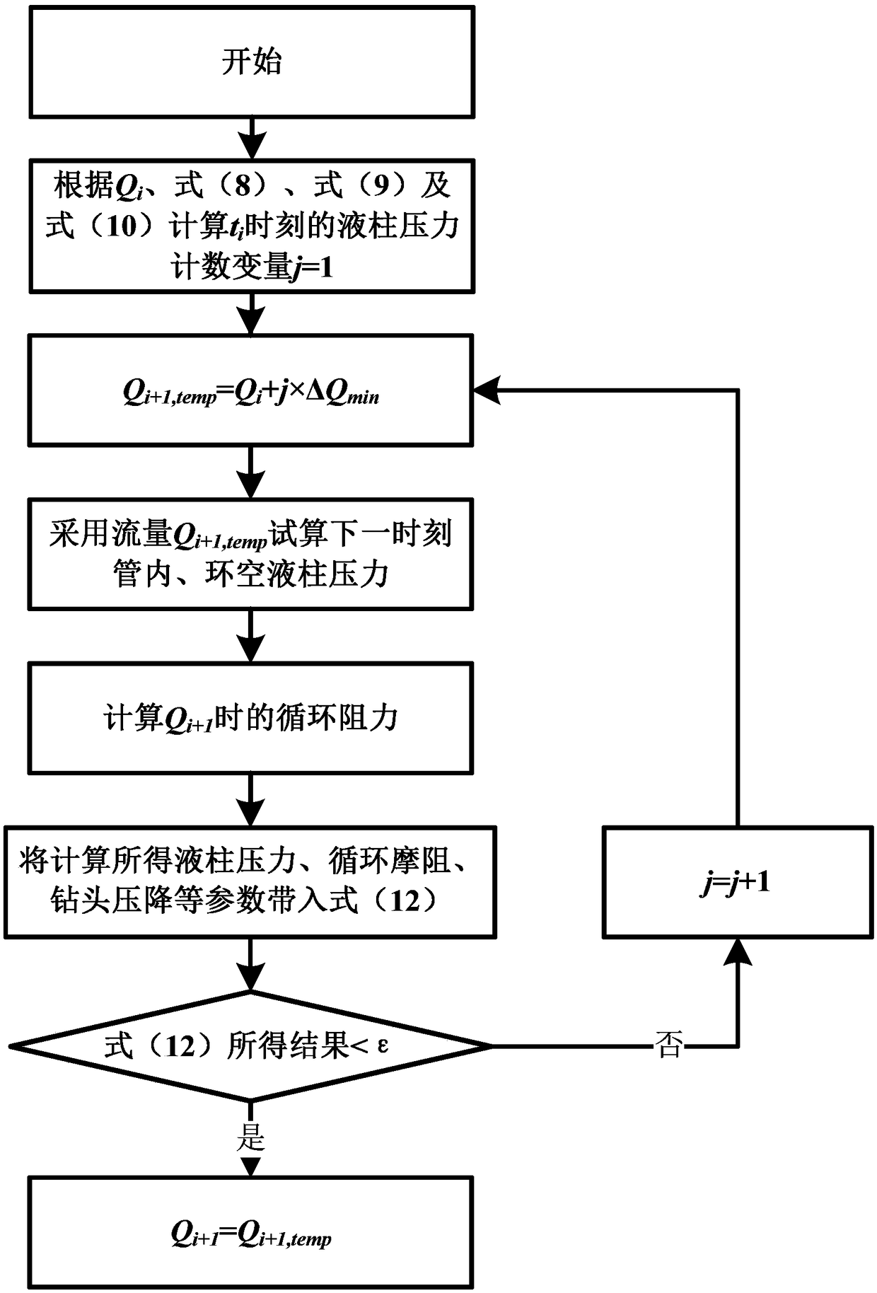
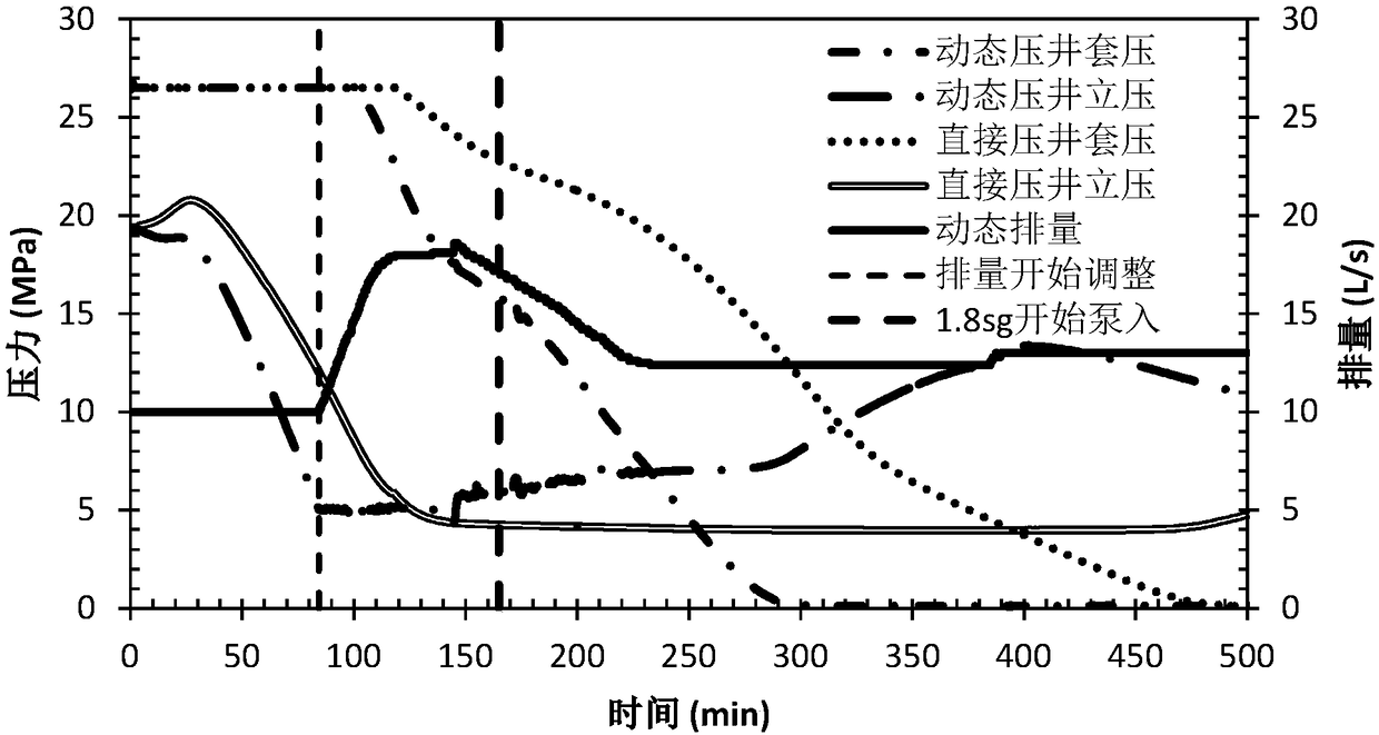
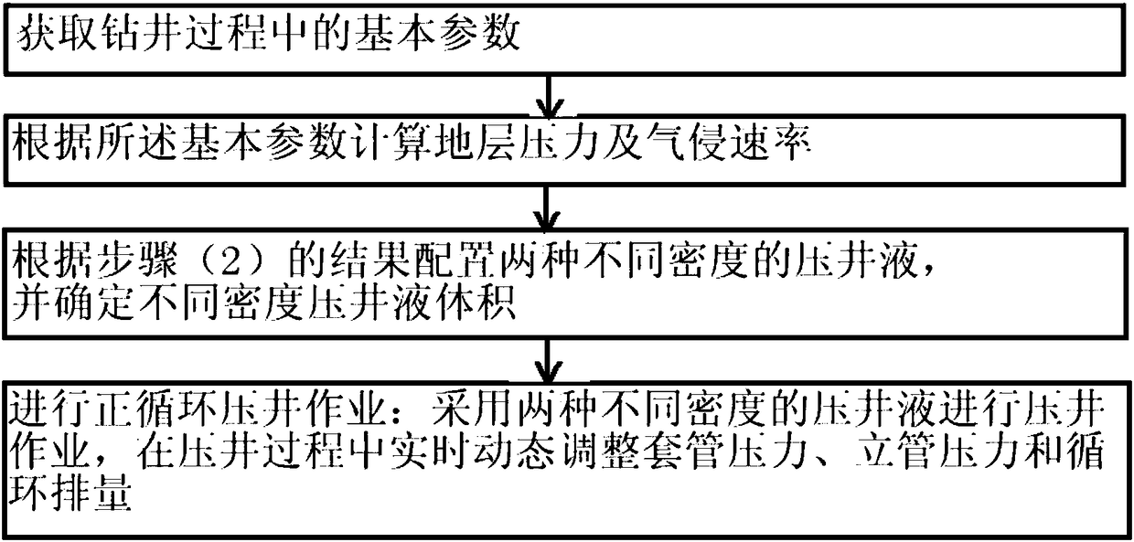
[0074] The invention proposes a dynamic parameter-variable well killing process method, which can meet the technical requirements for safe construction of deep and ultra-deep wells with gas invasion and well killing. The dynamic variable parameter killing method first determines the formation pressure coefficient according to the shut-in casing pressure, designs two kinds of density killing fluid, and determines the volume of killing fluid with different densities, and continuously pumps the killing fluid in stages to carry out the well killing operation. During the well process, the well killing displacement is adjusted in real time according to the changes of wellhead vertical pressure and casing pressure, so as to stabilize the formation as soon as possible. The implementation method is as follows: (1) first obtain the basic data of drilling and gas invasion, and c...


PUM


Abstract

The invention provides a method of dynamic and variable parameter well-killing technology, belonging to the field of safe well-drilling. The method comprises the following steps: (1) obtaining basic parameters during a well-drilling process; (2) calculating formation pressure and gas cut rate according to the basic parameters; (3) configuring two well-killing fluids with different densities according to a result of the step (2) and determining volumes of well-killing fluids with different densities; (4) performing positive-cycle well-drilling operation: adopting two well-killing fluids with different densities to perform well-killing operation. During a well-killing process, casing pressure, standpipe pressure and circulating displacement are adjusted in a dynamic and real-time manner. Themethod is easy in realization and good in well killing effect and can quickly reduce the risk of excessively high well head pressure. Compared with a conventional well-killing method, the method enjoys high success rate and can meet the requirement for safe well-killing operation in a high-temperature high-pressure deep well during gas cut.

Description

technical field [0001] The invention belongs to the field of safe drilling, and in particular relates to a dynamic parameter-variable well killing process, which is used for the safety control and discharge of compressed gas invasion and overflow when gas invasion and overflow occur in the drilling process of high-pressure gas wells. Background technique [0002] With the increasing demand for oil and gas resources in my country's economy and society, oil and gas exploration and development are gradually moving towards deep complex reservoirs. For example, the deep formations of Sichuan Basin and Tarim Basin contain rich oil and gas resources. Due to the ultra-deep burial of resources in these areas, the ultra-high pressure and temperature at the bottom of the well, a series of drilling problems have been caused, especially the problem of well control safety. [0003] For deep-buried marine carbonate reservoirs, the reservoir space is mostly pores and fractures, gas-liquid r...

Claims


Application Information

Patent Timeline
IPC IPC(8): E21B7/00E21B21/00E21B49/00E21B47/06
CPCE21B7/00E21B21/00E21B47/06E21B49/00
Inventor 牛新明周号博王果张进双范红康孙连忠陈小锋张建龙刘卫东刘建华
Owner CHINA PETROLEUM & CHEM CORP
Why Eureka
Try Eureka