Solid-state zoom lens-based non-contact laser thickness measuring device and method

A zoom lens, non-contact technology, applied in the field of optical measurement, can solve the problems of unfavorable portable or even handheld measurement, complicated device structure and operation method, high equipment price, etc. Effect

Active Publication Date: 2018-11-16
NAT UNIV OF DEFENSE TECH
View PDF13 Cites 7 Cited by
  • Summary
  • Abstract
  • Description
  • Claims
  • Application Information

AI Technical Summary

Problems solved by technology

[0004] In short, there are many methods to realize non-contact laser thickness measurement at present, most of which are based on coherent light interferometry, confocal measurement method or spectral analysis method. The device structure and operation method are complicated, which is not conducive to the realization of portable or even hand-held measurement. Sometimes a relatively expensive high-resolution spectrometer is needed, and the equipment is expensive, which is not conducive to popularization and application

Method used


Image

  • Solid-state zoom lens-based non-contact laser thickness measuring device and method
  • Solid-state zoom lens-based non-contact laser thickness measuring device and method
  • Solid-state zoom lens-based non-contact laser thickness measuring device and method

Examples


Embodiment Construction

[0054] The specific embodiments of the present invention will be further described below in conjunction with the accompanying drawings.

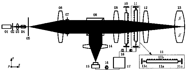
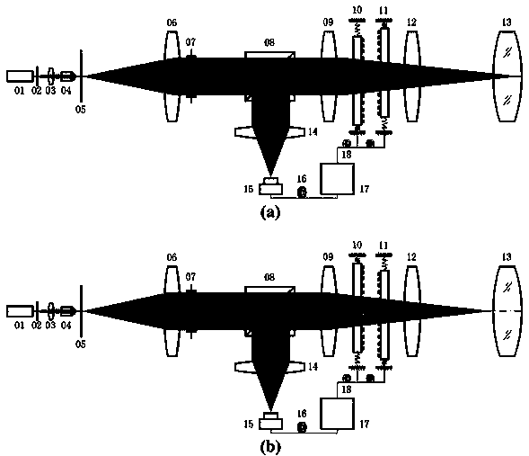
[0055] The present invention proposes a non-contact laser thickness measurement device and method based on a solid-state zoom lens, the device consists of a laser 01, an adjustable light intensity attenuator 02, a first collimator lens 03, a microlens 04, and a spatial filter 05 , the second collimator lens 06, the diaphragm 07, the dichroic prism 08, the first aberration correction lens 09, the first solid zoom lens assembly 10, the second solid zoom lens assembly 11, the second aberration correction lens 12, to be tested Object 13, focusing lens 14, photodetector 15, data transmission line 16, signal control, data processing and display module 17, and control signal transmission line 18. Take the second solid zoom lens assembly 11 as an example to illustrate the structural composition and working principle of the solid zoom lens assembly, ...


PUM

PropertyMeasurementUnit
Apertureaaaaaaaaaa
Sampling rateaaaaaaaaaa

Abstract

The invention belongs to the optical measurement field and relates to a solid-state zoom lens-based non-contact laser thickness measuring device and method. The device is composed of a laser, a lightintensity adjustable attenuator, a first collimating lens, a micro lens, a spatial filter, a second collimating lens, a diaphragm, a beam splitting prism, a first aberration correcting lens, a first solid-state zoom lens assembly, a second solid-state zoom lens assembly, a second aberration correcting lens, an object to be tested, a focusing lens, a photoelectric detector, a data transmission line, a signal control, data processing and display module, and a control signal transmission line. The solid-state zoom lens-based non-contact laser thickness measuring device of the invention is simplerand more compact than a conventional zoom lens group; and the solid-state zoom lens-based non-contact laser thickness measuring device of the invention is more stable, has superior performance, and is close to a diffraction limit compared with a liquid lens. According to the solid-state zoom lens-based non-contact laser thickness measuring device and method, the focal length of the solid-state zoom lens can be adjusted through a full-electronically controlled closed-loop, so that the focusing position of an outgoing beam on the object to be tested is changed; the position of the maximum valueof reflected light intensity is recorded through using a laser self-collimation effect; and therefore, the thickness measurement of the object to be measured can be realized, and the object to be measured is not required to be accurately moved or adjusted during a measurement process.

Description

technical field [0001] The invention relates to the field of optical measurement, in particular to a non-contact laser thickness measuring device based on a solid-state zoom lens and a method for using it. Background technique [0002] The non-contact laser thickness measuring device measures the thickness of the object to be measured (usually a light-transmitting material) by optical means, without using any probe to touch the surface of the object to be measured, avoiding the possibility of scratching the surface of the object to be measured. Compared with contact measurement With unique advantages, it is widely used in optical device processing, high-end glass manufacturing, and precision optical system assembly and testing. [0003] In recent years, various devices and methods have been invented to realize non-contact thickness measurement. Chinese invention patent "High-precision optical spacing measurement device and measurement method" (ZL201410472652.5) ​​is based o...

Claims


Application Information

Patent Timeline
IPC IPC(8): G01B11/06
CPCG01B11/06
Inventor 邹永超王俊陈祥国徐攀赵学谦马丽娜胡正良
Owner NAT UNIV OF DEFENSE TECH
Why Eureka
Try Eureka