Convenient setting-out device for angle measurement
A technology of pay-off device and angle measurement, applied in the direction of measuring device, measuring gauge, gauge for measuring angle/taper, etc., can solve the problem of increased workload, contamination of ink storage sponge of ink cartridge, ink not well absorbed on the line, etc. The problem is to improve the efficiency and accuracy of the pay-off, the structure of the device is simple and compact, and it is convenient for the pay-off measurement work.
- Summary
- Abstract
- Description
- Claims
- Application Information
AI Technical Summary
Problems solved by technology
Method used
Image
Examples
Embodiment 1
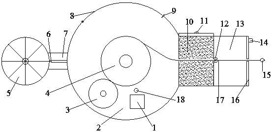
[0019] Embodiment 1: see figure 1 , a convenient angle measurement pay-off device, the pay-off device includes a power storage group 1, a wire box 2, a wire reel frame 4, an angle plate 5, a pointer 6, a belt shaft 7, a wire box cover 8, and an ink storage box 10 , the dirt collecting box 13, the wire 17 and the drive assembly, the power storage group 1 is embedded in the wire box 2, the wire reel frame 4 is installed in the wire box 2, the angle plate 5 is fixedly installed on the end of the belt shaft 7, and the pointer 6 is fixedly installed in the middle of the belt shaft 7, and the direction of the arrow points to the angle plate 5; the front end of the belt shaft 7 is fixedly connected to the center line of the line box 2, and the rear end is movably connected to the angle plate 5; the line box cover 8 is movably installed in the line box 2, fixed by buckle 9 and wire box 2; one end of the ink storage box is connected to the wire box, the other end is connected to the di...
Embodiment 2
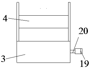
[0020] Example 2: see figure 1 , figure 2 , as an improvement of the present invention, the drive assembly includes a drive wheel 3, a take-up control switch 18, a drive motor 19 and a drive shaft 20, and the drive wheel 3 is installed in the wire box 2 through the drive shaft 20 and the drive motor 19 connected; the power storage group is embedded and installed in the wire box body, and is connected with the drive motor and the limit control switch through wires. When the power is used up, you can directly plug in the USB cable for charging to provide power for the drive motor.
Embodiment 3
[0021] Embodiment 3: see figure 1 , figure 2 , as an improvement of the present invention, the wire box 2 is a cylindrical structure, the front end is fixedly connected to the ink storage box 10 and the dirt collection box 13, and the rear end is fixedly connected to the belt shaft 7. The driving wheel is cylindrical and made of rubber material, installed on the drive shaft.
PUM
 Abstract
Description
Claims
Application Information
 - R&D
- Intellectual Property
- Life Sciences
- Materials
- Tech Scout
- Unparalleled Data Quality
- Higher Quality Content
- 60% Fewer Hallucinations
Browse by: Latest US Patents, China's latest patents, Technical Efficacy Thesaurus, Application Domain, Technology Topic, Popular Technical Reports.
© 2025 PatSnap. All rights reserved.Legal|Privacy policy|Modern Slavery Act Transparency Statement|Sitemap|About US| Contact US: help@patsnap.com


