Supercharge Your Innovation With Domain-Expert AI Agents!

Radar tachymeter

A radar speedometer and radar technology, applied in the field of speedometers, can solve the problems of affecting the shooting effect, inconvenient operation, time-consuming and laborious, etc.

Inactive Publication Date: 2018-11-16
WUHU HANGFEI SCI & TECH
View PDF5 Cites 1 Cited by
  • Summary
  • Abstract
  • Description
  • Claims
  • Application Information

AI Technical Summary

Problems solved by technology

[0005] In view of the above-mentioned technical problems, the purpose of the present invention is to overcome the problem that when the radar speedometer in the prior art is used outdoors for a long time, it is easy to accumulate dust on the camera, thereby affecting the shooting effect, requiring manual cleaning, inconvenient operation, and time-consuming and labor-intensive problems. Thereby providing a radar speedometer that can automatically clean the camera on the speedometer during use to ensure normal use and requires manual cleaning

Method used


Image

  • Radar tachymeter
  • Radar tachymeter
  • Radar tachymeter

Examples


Embodiment Construction

[0027] Specific embodiments of the present invention will be described in detail below in conjunction with the accompanying drawings. It should be understood that the specific embodiments described here are only used to illustrate and explain the present invention, and are not intended to limit the present invention.

[0028] In the present invention, in the absence of a contrary statement, the orientation words included in the term, such as "upper, lower, inner, outer", etc., only represent the orientation of the term in the normal use state, or are understood by those skilled in the art. colloquial term and should not be construed as a limitation of the term.

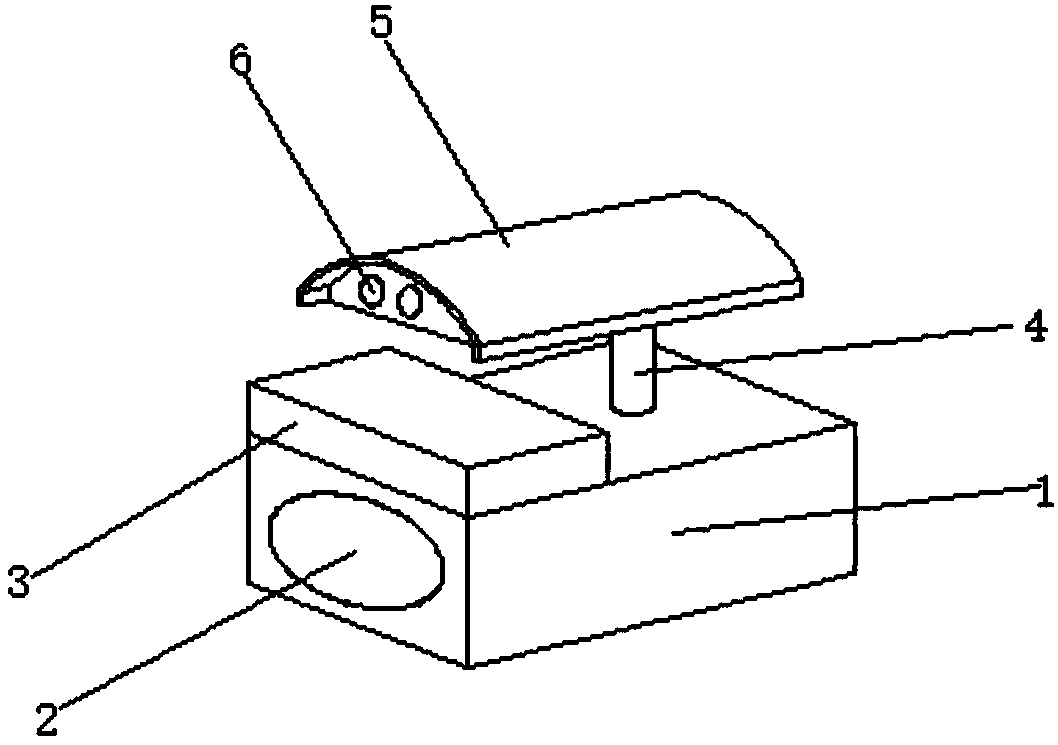
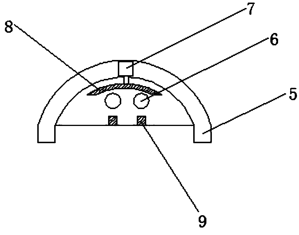
[0029] Such as Figure 1-4 As shown, the present invention provides a radar speedometer, which includes: a control box 1, a radar body 2, a protective cover 5 and a camera 6; the radar body 2 is arranged on the control box 1 , the camera 6 is arranged on the upper surface of the control box 1 through the support col...


PUM


Abstract

The invention discloses a radar tachymeter comprising: a control box body, a radar body, a protective cover and a camera. The radar body is arranged on the control box body. The camera is arranged onthe upper surface of the control box body through a support column and is provided with the protective cover. A first driving pump is disposed in the protective cover. A piston rod on the first driving pump is vertically disposed. The bottom end of the piston rod is connected with a cleaning plate. One side of the cleaning plate is abutted against the camera. The first driving pump is capable of driving the cleaning plate to move in a vertical direction. The radar tachymeter solves the problem that dust is liable to accumulate on the camera of a radar tachymeter in the prior art used outdoorsfor a long time and thus affects a shooting effect, requires manual cleaning, is inconvenient in operation, and wastes time and labor.

Description

technical field [0001] The invention relates to the field of speedometers, in particular to a radar speedometer. Background technique [0002] The speed radar mainly uses the Doppler Effect principle: when the target approaches the radar antenna, the frequency of the reflected signal will be higher than that of the transmitter; conversely, when the target moves away from the antenna, the frequency of the reflected signal will be lower than the frequency of the transmitted signal. probability. In this way, the relative speed between the target and the radar can be calculated by changing the value of the frequency, which is widely used in the transportation department. [0003] When the radar speedometer in the prior art is used outdoors for a long time, dust is easy to accumulate on the camera, thereby affecting the shooting effect, requiring manual cleaning, inconvenient operation, and time-consuming and laborious. [0004] Therefore, it is an urgent problem to be solved b...

Claims


Application Information

Patent Timeline
IPC IPC(8): G01S13/58
CPCG01S13/58
Inventor 王威邓禹陈坤舒航张家巍宋旋宋琪
Owner WUHU HANGFEI SCI & TECH
Features
  • R&D
  • Intellectual Property
  • Life Sciences
  • Materials
  • Tech Scout
  • Unparalleled Data Quality
  • Higher Quality Content
  • 60% Fewer Hallucinations
Learn More