
Separation Control Method Based on Parameter Identification

A separate control and parameter identification technology, applied in the field of separate control based on parameter identification, can solve problems such as difficulty in ensuring convergence, difficulty in application, and complex algorithms, and achieve the effect of avoiding algorithm non-convergence and poor real-time performance

Active Publication Date: 2021-11-12
BEIJING AEROSPACE TECH INST
View PDF7 Cites 0 Cited by
  • Summary
  • Abstract
  • Description
  • Claims
  • Application Information

AI Technical Summary

Problems solved by technology

The general disadvantages of these methods are that the algorithm is complex, the demand for computing resources is large, and the convergence is often difficult to guarantee in the actual application process. It is generally suitable for slowly changing industrial processes, and it is difficult to truly apply to the aircraft control system.

Method used


Image

  • Separation Control Method Based on Parameter Identification
  • Separation Control Method Based on Parameter Identification
  • Separation Control Method Based on Parameter Identification

Examples


Embodiment Construction

[0037] It should be noted that, in the case of no conflict, the embodiments in the present application and the features in the embodiments can be combined with each other. The following will clearly and completely describe the technical solutions in the embodiments of the present invention with reference to the accompanying drawings in the embodiments of the present invention. Obviously, the described embodiments are only some, not all, embodiments of the present invention. The following description of at least one exemplary embodiment is merely illustrative in nature and in no way taken as limiting the invention, its application or uses. Based on the embodiments of the present invention, all other embodiments obtained by persons of ordinary skill in the art without creative efforts fall within the protection scope of the present invention.

[0038] It should be noted that the terminology used here is only for describing specific implementations, and is not intended to limit t...


PUM


Abstract

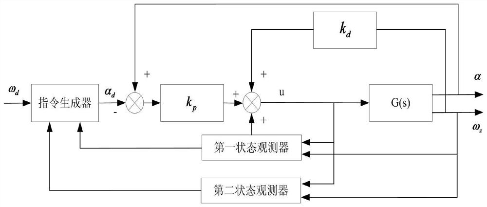
The present invention proposes a separate control method based on parameter identification, and establishes a longitudinal controlled object model; designing a control strategy based on the established model includes: designing an attack angle instruction profile based on an equal pitch angle velocity instruction, and according to the attack angle instruction The profile generates an angle of attack command for controlling the controlled object; designing the first state observer and the second state observer to observe the controlled object to identify the stable zero-control equilibrium state of the controlled object; and designing the The first state observer is also used for stable control of the controlled object; after the controlled object enters the stable zero-control equilibrium state, the angle-of-attack command is switched to the corresponding attack angle command at the initial moment of entering the stable zero-control equilibrium state. The control method of the invention effectively realizes the identification and stable control of the stable equilibrium state of the aircraft, and avoids the problems of algorithm non-convergence and poor real-time performance in the existing identification method.

Description

technical field [0001] The invention relates to the technical field of aircraft control, in particular to a separation control method based on parameter identification. Background technique [0002] Existing hypersonic vehicles mostly adopt boost + cruise two-stage flight mode. The purpose of the booster stage is to send the load into the predetermined transfer window. In order to save weight and energy, most of the thrust reversers are not used. Therefore, in order to successfully realize the separation between the stages, the separation command must be issued at the end of the thrust. At the same time, for the aircraft that only achieves attitude stability control through thrust vector during the boosting process, facing the problems of insufficient control ability and large uncertainty in the later stage of thrust trailing, it is necessary to choose a statically stable equilibrium state where the torque is zero in the uncontrolled state. achieve stability control. Affec...

Claims


Application Information

Patent Timeline
Patent Type & Authority Patents(China)
IPC IPC(8): G05B13/04
CPCG05B13/042
Inventor 魏振岩魏毅寅吴森堂姚德清尤伟帅姜丽敏覃鹤宏王昊徐宝华
Owner BEIJING AEROSPACE TECH INST
Learn More