Method and device for obtaining vehicle positioning information

A vehicle positioning and positioning information technology, applied in the field of vehicle positioning, can solve problems such as obstacles in the research and promotion of automatic driving technology, lack of methods for positioning information, etc., and achieve the effect of improving automatic driving and accurate positioning

Active Publication Date: 2018-11-16
禾多科技(北京)有限公司
View PDF3 Cites 5 Cited by
  • Summary
  • Abstract
  • Description
  • Claims
  • Application Information

AI Technical Summary

Benefits of technology

This technology helps vehicles navigate safely without colliding into obstacles or other road users during their journey. It uses factors like navigational status (the distance from one point) along its route to calculate optimal values that represent these constraints over different points within it's path. These optimum values help drivers keep track of where they have been located throughout this entire course of travel. Overall, this system improves efficiency and safety autonomous car performance while reducing human error caused by driver errors.

Problems solved by technology

The technical problem addressed by this patented method relates to improving self-drive cars' ability to accurately locate their own position on roadways during autonomous operation without relying solely upon GPS signals alone.

Method used


Image

  • Method and device for obtaining vehicle positioning information
  • Method and device for obtaining vehicle positioning information
  • Method and device for obtaining vehicle positioning information

Examples


no. 1 example

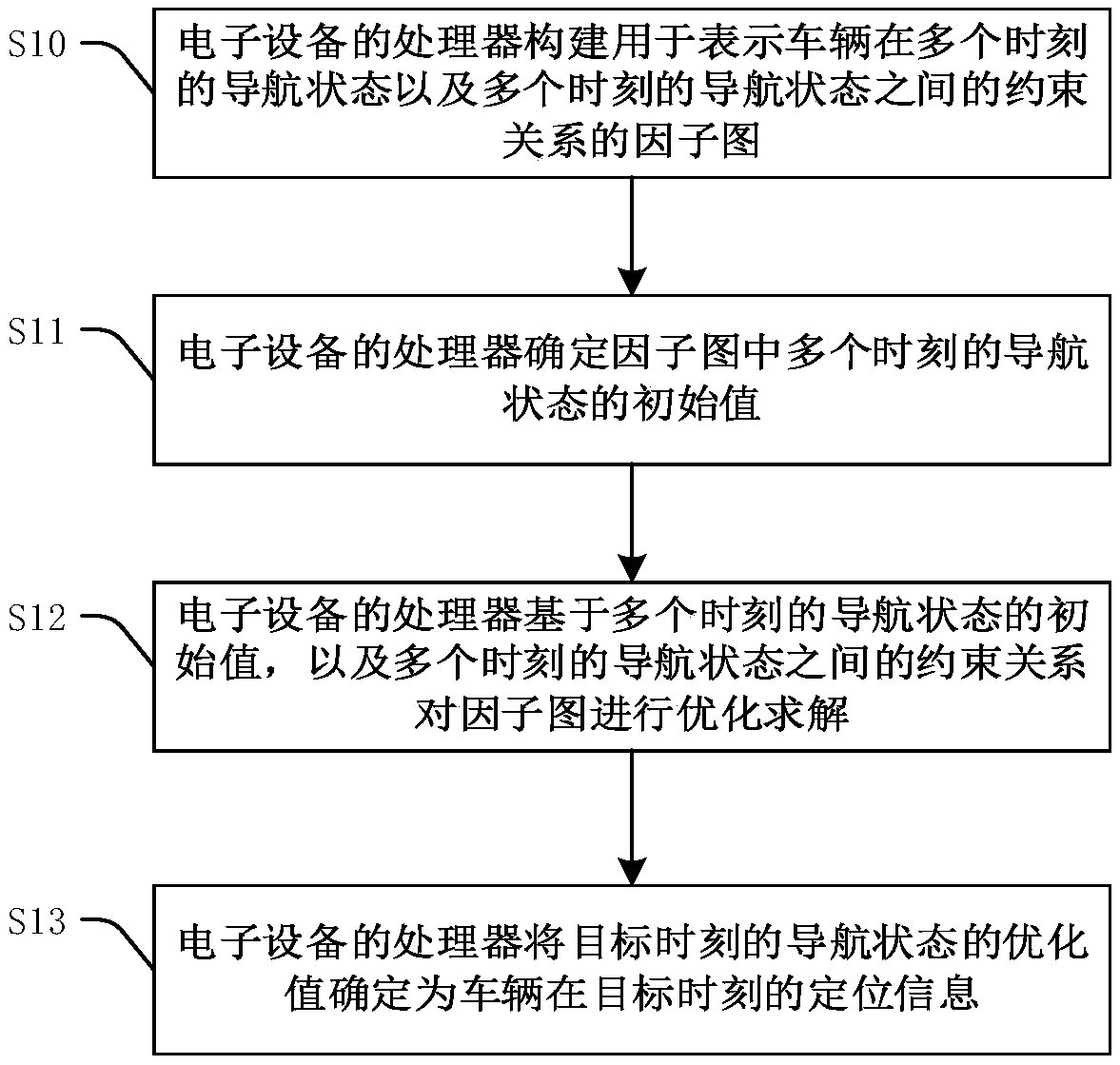
[0067] figure 2 A flow chart of the method for obtaining vehicle location information provided by the first embodiment of the present invention is shown. refer to figure 2 , methods for obtaining vehicle location information include:

[0068] Step S10: The processor 106 of the electronic device 100 builds a factor graph for representing the navigation state of the vehicle at multiple times and the constraint relationship among the navigation states at multiple times.

[0069] The navigation state at each moment includes three parameters: the vehicle's pose, velocity, and zero offset of the inertial measurement unit (IMU) at that moment. The values ​​of the above three parameters can be obtained by obtaining their original observations through equipment or systems installed on the vehicle, and then combining with the method provided by the first embodiment to optimize and solve them. Equipment or systems that can be used to collect observations include, but are not limited...

no. 2 example

[0121] Figure 4 A functional block diagram of the device 200 for obtaining vehicle location information provided by the second embodiment of the present invention is shown. refer to Figure 4 , the device includes a factor graph construction module 210 , an initial value determination module 220 , a factor graph solution module 230 and a location information determination module 240 .

[0122] Wherein, the factor graph construction module 210 is used to construct the factor graph used to represent the vehicle's navigation state at multiple moments and the constraint relationship between the navigation states at multiple moments, wherein, the navigation state at each moment includes the vehicle at the The pose, velocity, and zero offset of the IMU at each moment, multiple moments including the target moment;

[0123] The initial value determination module 220 is used to determine the initial value of the navigation state at multiple moments in the factor graph;

[0124] The...

no. 3 example

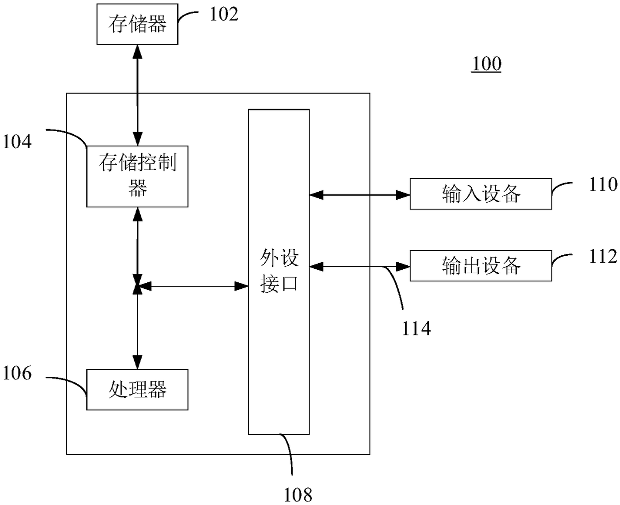
[0128] The third embodiment of the present invention provides a computer storage medium. Computer program instructions are stored in the computer storage medium. When the computer program instructions are read and run by the processor of the computer, the method for obtaining vehicle positioning information provided by the embodiment of the present invention is executed. . The computer storage medium can be implemented as, but not limited to figure 1 Memory 102 is shown.


PUM


Abstract

The invention relates to the technical field of vehicle positioning, and provides a method and device for obtaining vehicle positioning information. According to the method, firstly, navigation states representing a vehicle at a plurality of moments and a factor graph representing a constraint relation among the navigation states at the plurality of moments are constructed, and then an initial value of the navigation states of the plurality of moments in the factor graph is determined, and finally based on the initial value of the navigation states at the plurality of moments, and the constraint relation among the navigation states at the plurality of moments, the factor graph is optimized and solved, and further, the optimization value of the navigation state of a target moment in the plurality of moments is determined as the positioning information of the vehicle at the target time. According to the method, since the constraint relation among the navigation states is fully taken into account, the optimization value of the obtained navigation state can accurately estimate the real navigation state of the vehicle at the target time, and therefore, the optimization value is used asthe positioning information of the vehicle at the target time, the accurate positioning of the vehicle can be achieved and the effect of automatic driving can be improved.

Description


Claims


Application Information

Patent Timeline
Owner 禾多科技(北京)有限公司
Why Eureka
Try Eureka