A wireless energy transmission system and method based on direction retroactive antenna

A technology of wireless energy transmission and direction backtracking, applied in the direction of circuit devices, electrical components, etc., can solve the problems of difficult circuit phase consistency control, low phase control accuracy, and the influence of backtracking wave directivity, so as to avoid two space Accurate and high-pointing precision wireless energy transmission effect of attenuation and improvement of directivity of traceback signals

Active Publication Date: 2021-12-03
XIDIAN UNIV
View PDF4 Cites 0 Cited by
  • Summary
  • Abstract
  • Description
  • Claims
  • Application Information

AI Technical Summary

Problems solved by technology

All the above-mentioned implementation methods, after receiving the pilot signal, conjugate the pilot signal to form a backtracking signal, so that the signal will go through two space attenuations, the power of the backtracking signal is weak when it reaches the receiving end, and the phase control accuracy is not high
[0003] In summary, the problems in the prior art are: According to the Fries transmission formula, under the condition of fixed antenna aperture and gain, the power received by the receiving end decreases with the increase of the transmission distance of electromagnetic waves.
And during long-distance transmission, the influence of the power divider, amplifier and mixer in the circuit on the phase of the retrospective wave will have a great impact on the directivity of the retroactive wave
It is very difficult to control the phase consistency in the circuit, and the coupling between the links will also affect the system performance

Method used


Image

  • A wireless energy transmission system and method based on direction retroactive antenna
  • A wireless energy transmission system and method based on direction retroactive antenna
  • A wireless energy transmission system and method based on direction retroactive antenna

Examples


Embodiment Construction

[0046] In order to make the object, technical solution and advantages of the present invention more clear, the present invention will be further described in detail below in conjunction with the examples. It should be understood that the specific embodiments described here are only used to explain the present invention, not to limit the present invention.

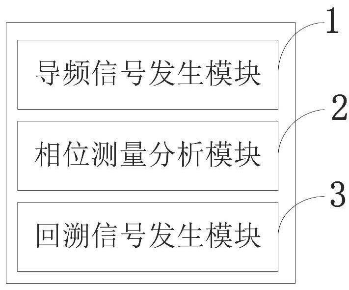
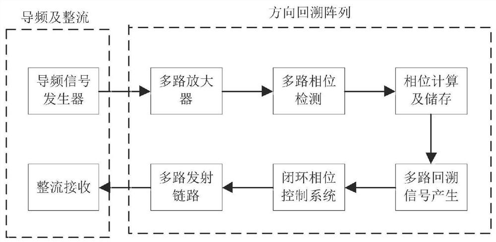
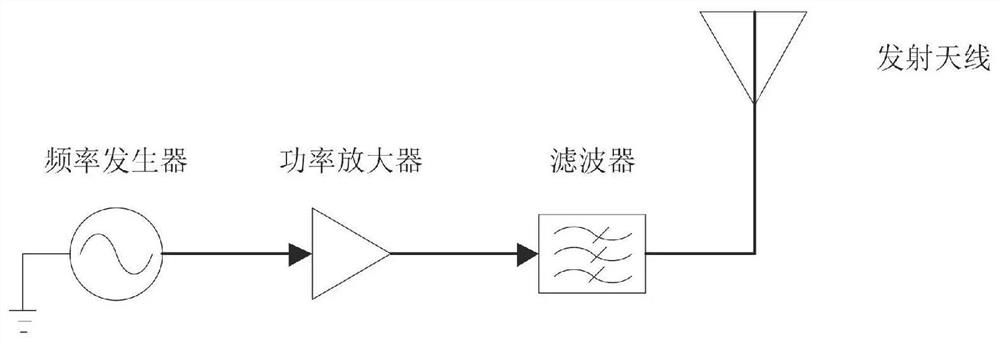
[0047] Based on the principle of phase conjugation, the present invention improves the deficiencies of the original technology, adopts the phase measurement and analysis module to collect and analyze the phase information of the pilot signal, and generates a backtracking signal by the frequency generator, effectively avoiding the signal twice Space attenuation greatly increases the power of the traceback wave; and a closed-loop phase control system is added to the traceback signal generator to calibrate the phase of the traceback signal in real time, so that the directivity of the traceback signal is guaranteed. The inventi...


PUM


Abstract

The invention belongs to the field of antenna array or system technology, and discloses a wireless energy transmission system and method based on a direction-retrospective antenna. A pilot signal generation module generates a pilot signal, and a phase measurement and analysis module collects and analyzes the signal phase. The signal generation module and the closed-loop phase control unit output high-pointing precision back-tracking waves, and the rectenna and the circuit convert electromagnetic energy. The invention overcomes the deficiencies of the two-way signal attenuation and pointing precision in the prior art, and greatly improves the power of the backtracking signal. The present invention adopts the phase measurement and analysis module to collect and analyze the phase information of the pilot signal, and the frequency generator generates the backtracking signal, which effectively avoids the two space attenuation of the signal and greatly improves the power of the backtracking wave; and in the backtracking signal generator A closed-loop phase control system is added to calibrate the phase of the traceback signal in real time, so that the directivity of the traceback signal is guaranteed.

Description

technical field [0001] The invention belongs to the technical field of antenna arrays or systems, and in particular relates to a wireless energy transmission system and method based on a direction-retrospective antenna. Background technique [0002] At present, the existing technologies commonly used in the industry are as follows: Wireless energy transmission technology refers to a technology that transmits energy to the terminal without the need for wires. The main implementation methods include: inductive coupling, electromagnetic resonance coupling, ultrasonic, laser, and microwave. Inductive coupling and electromagnetic resonance coupling have large transmission power, respectively use coil coupling and strong electromagnetic coupling between electromagnetic resonance objects to transmit energy, but the transmission distance is limited; ultrasonic waves can only propagate through various coals, and have a large attenuation in the air. The transmission efficiency is low...

Claims


Application Information

Patent Timeline
Patent Type & Authority Patents(China)
IPC IPC(8): H02J50/20H02J50/80
CPCH02J50/20H02J50/80
Inventor 陈蕾杨曜州方凌史小卫
Owner XIDIAN UNIV
Why Eureka
Try Eureka